- Joined
- Aug 7, 2014
- Messages
- 321
- Reaction score
- 182
After reading Kal's book from The Electric Brewery about six or seven times in the past year, and thinking a few things through, there are some changes that I wanted to make to his design to suit my own brewing needs/wishes.
My basic equipment plan is for two 30-gallon uninsulated kettles for HLT and boil, and one 20-gallon insulated mash tun. The target is for ½ bbl brews.
Safety first: I am going to use a double-pole 50A GFCI breaker from my garage subpanel to supply the brew panel. Does anyone know the mA rating of the residual current trip threshold for a Square D QO-series 50A DP GFCI breaker? I can't find it anywhere.
Although I haven't added it to the schematic yet, I'm going to install a safety microswitch that will kill everything except the incoming leads going to the main contactor, as soon as the door is opened. I also added an E-stop button to the panel face, just in case.
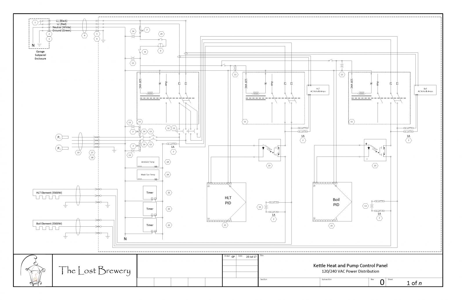
Another significant change I made is that I added overcurrent protection in a lot of spots I felt the TEB guy was missing it. His pics show 14AWG wire tied to the same terminal as the incoming 10AWG feed cable, and the 14 AWG wire goes off into the sunset without any fusing.
I'm not a big fan of enclosure space lost by using the doorbell transformers and the 24VDC power supplies, so I specified all 120VAC control power (hence the door-open kill switch). I also bumped the enclosure size up to a Rittal 20" x 24" x 8" box.
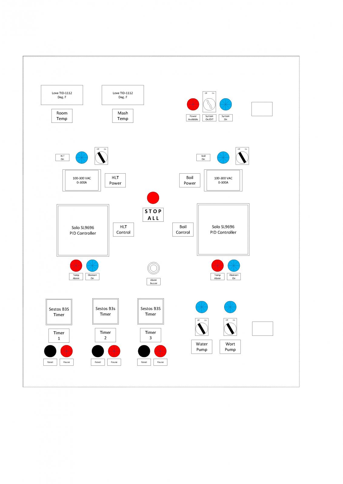
I found PID controllers in a ¼ DIN (96mm) size. I think my eyes will thank me. They also have Modbus capability, so if I get frisky and want to automate later on, it will be easier.
My design is for a HERMS system, so I ditched the third PID in favor of a Love TID-1112 temp display. I also added a second TID-1112 to measure the ambient air temp. I want to start noting the effect of hot, muggy South Florida summer brew days on my brews.
I also found meters that measure 80-300 VAC and 0-100A. I used two of them in my layout. One measures the voltage of the HLT side of the system and the amperage of the incoming L1 feed cable. The other meter measures the voltage of the Boil side and the amperage of the incoming L2 feed cable. That will let me know if I wind up with some bizarre L1-L2 imbalance.
On brew days, I find I have timers going all over the place, so instead of kicking my iPad around the brewery, I added two more ⅛ DIN timers.
My take on his design is for a 50A feed to supply two 5500W elements simultaneously. Not sure if I'll use it, but I'm only going to do this once.
I'm also going to use DIN rail equipment and 1" w x 2" h finger-sided tray with snap-on covers inside the enclosure wherever possible. I like a nice, tidy appearance, and that seems to wind up looking the nicest, with the least amount of effort.
I have three more drawings to produce before I'm comfortable enough to place orders and pick up a grinder: A control and signal diagram is one missing drawing, as are enclosure layout and hookup diagrams. I also need to go through and number all of the wires on the attached schematic.
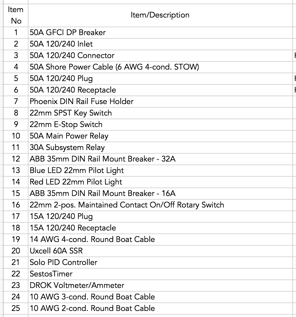
I've attached 3 files. One is a panel face layout, the second is a schematic of the power distribution (a bitch to get into PNG format). The third pic is a BOM key for the hexagonal callouts in the schematic.
It would be awesome to get feedback on what I've missed!


Last edited:


![Craft A Brew - Safale BE-256 Yeast - Fermentis - Belgian Ale Dry Yeast - For Belgian & Strong Ales - Ingredients for Home Brewing - Beer Making Supplies - [3 Pack]](https://m.media-amazon.com/images/I/51bcKEwQmWL._SL500_.jpg)


