Does anyone have the wiring diagram for the Electric Brewing Supply - 360 Series 2-element Control Panel. I have 240V thorough out the controller until it gets to the DIN Rail Connecter going to my HLT and BK element plug inlet. With a regular multi meter it reads fine but with a LoZ meter, it is not getting the correct voltage. I looked on the site but did not see any for this model. Thanks
You are using an out of date browser. It may not display this or other websites correctly.
You should upgrade or use an alternative browser.
You should upgrade or use an alternative browser.
Electric Brewing Supply - 360 Series 2-element Control Panel
- Thread starter lmr275rgr
- Start date

Help Support Homebrew Talk:
This site may earn a commission from merchant affiliate
links, including eBay, Amazon, and others.


Did you actually have a problem with the operation of the controller? I'm 99% sure that Low Z mode doesn't work on SCR (how the SSR works) circuits. What if you set the meter to AC volts?
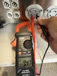
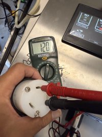
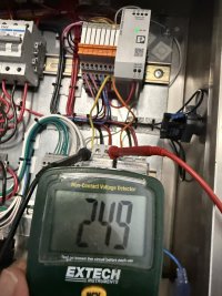
The reason your image1(2) is correctly showing 120v between L1 and Ground is that it's the hot line that DOESN'T go through the SSR.
In other words, it looks like you don't have a problem.
The reason your image1(2) is correctly showing 120v between L1 and Ground is that it's the hot line that DOESN'T go through the SSR.
In other words, it looks like you don't have a problem.
.
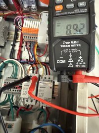
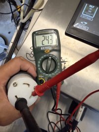
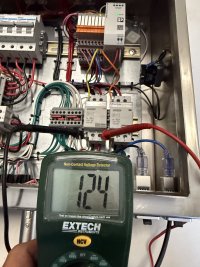
Hope this makes sense. With a Voltage Meter I check the end of the end of the element power cord and get 240V between the two hot (white and black) and 124 between ground and hot (green and black, green and white). (All is good) When I connect it to a 240V, 5500w element (partially plugged in) and check with a load on it, both hot black and white are 0 volts and both hot with ground are 124V.Did you actually have a problem with the operation of the controller? I'm 99% sure that Low Z mode doesn't work on SCR (how the SSR works) circuits. What if you set the meter to AC volts?
The reason your image1(2) is correctly showing 120v between L1 and Ground is that it's the hot line that DOESN'T go through the SSR.
In other words, it looks like you don't have a problem.
Is that when the meter is in LOW Z mode or set to AC volts?
When you put a load on the cable with the element, does it heat when the controller is calling for heat?
If not, can you verify that the SSR is getting 12 VDC on the control terminals?
If yes, can you verify that the red LED on the SSR is lit?
When you put a load on the cable with the element, does it heat when the controller is calling for heat?
If not, can you verify that the SSR is getting 12 VDC on the control terminals?
If yes, can you verify that the red LED on the SSR is lit?
Your readings appear to be consistent with an SSR that is not turning on, so @Bobby_M 's advice to look at the input voltage on the SSR control inputs (terminals 3 & 4) is a good place to start. The SSR should turn on if the control input voltage is greater than 3V (DC), even tho the nominal voltage for most PID control outputs is ~12V. If the light on the SSR comes on, that just means that the SSR is receiving an adequate control input. It does not mean that the SSR is actually working, as the TRIAC, which is the actual power switch, is electrically isolated from the control input (they are optically coupled.) If the TRIAC, or it's triggering circuit in the SSR, has failed, the light on the SSR will still come on when a valid control voltage is applied.
If you want to test the SSR independently of the PID, you can disconnect the wires from SSR terminals 3 & 4, and connect a nine volt battery (make sure you get the polarity right) to terminals 3 & 4, which should turn the SSR on unless it has failed. With this test you should measure ~240 volts across L1 & L2 at the element (partially plugged in.)
Brew on


![Craft A Brew - Safale S-04 Dry Yeast - Fermentis - English Ale Dry Yeast - For English and American Ales and Hard Apple Ciders - Ingredients for Home Brewing - Beer Making Supplies - [1 Pack]](https://m.media-amazon.com/images/I/417FujUfrWL._SL500_.jpg)

$58.16
HUIZHUGS Brewing Equipment Keg Ball Lock Faucet 30cm Reinforced Silicone Hose Secondary Fermentation Homebrew Kegging Brewing Equipment
xiangshuizhenzhanglingfengshop

$82.50
Wilbur Curtis Brew Cone Assembly with Splash Pocket, High Volume - Commercial-Grade Brew Basket - WC-3422 (Each)
Global Commercial Parts


$53.24
1pc Hose Barb/MFL 1.5" Tri Clamp to Ball Lock Post Liquid Gas Homebrew Kegging Fermentation Parts Brewer Hardware SUS304(Gas MFL)
yunchengshiyanhuqucuichendianzishangwuyouxiangongsi


$53.24
1pc Hose Barb/MFL 1.5" Tri Clamp to Ball Lock Post Liquid Gas Homebrew Kegging Fermentation Parts Brewer Hardware SUS304(Gas Hose Barb)
Guangshui Weilu You Trading Co., Ltd


$10.99 ($31.16 / Ounce)
Hornindal Kveik Yeast for Homebrewing - Mead, Cider, Wine, Beer - 10g Packet - Saccharomyces Cerevisiae - Sold by Shadowhive.com
Shadowhive


$39.22 ($39.22 / Count)
Brewer's Best Home Brew Beer Ingredient Kit - 5 Gallon (Mexican Cerveza)
Home Brew Ohio


$20.94
$29.99
The Brew Your Own Big Book of Clone Recipes: Featuring 300 Homebrew Recipes from Your Favorite Breweries
Amazon.com


$176.97
1pc Commercial Keg Manifold 2" Tri Clamp,Ball Lock Tapping Head,Pressure Gauge/Adjustable PRV for Kegging,Fermentation Control
hanhanbaihuoxiaoshoudian


$33.99 ($17.00 / Count)
$41.99 ($21.00 / Count)
2 Pack 1 Gallon Large Fermentation Jars with 3 Airlocks and 2 SCREW Lids(100% Airtight Heavy Duty Lid w Silicone) - Wide Mouth Glass Jars w Scale Mark - Pickle Jars for Sauerkraut, Sourdough Starter
Qianfenie Direct

$22.00 ($623.23 / Ounce)
AMZLMPKNTW Ball Lock Sample Faucet 30cm Reinforced Silicone Hose Secondary Fermentation Homebrew Kegging joyful
无为中南商贸有限公司
used voltage meter. End of element power cord has 240V on hots, and 124V and 120 on other to legs. When I plug in element it does not get hot. With 0V hots and 123V on other two legs.Is that when the meter is in LOW Z mode or set to AC volts?
When you put a load on the cable with the element, does it heat when the controller is calling for heat?
If not, can you verify that the SSR is getting 12 VDC on the control terminals?
If yes, can you verify that the red LED on the SSR is lit?
Attachments
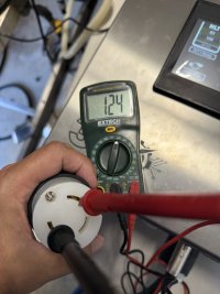
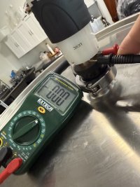
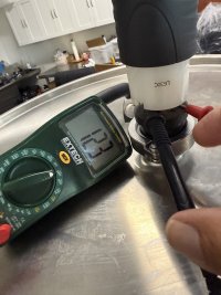
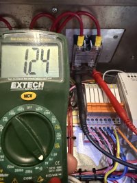
Thanks. The SSR light does not turn on and getting 1.24V. How does the PID affect the SSR. @Bobby_MYour readings appear to be consistent with an SSR that is not turning on, so @Bobby_M 's advice to look at the input voltage on the SSR control inputs (terminals 3 & 4) is a good place to start. The SSR should turn on if the control input voltage is greater than 3V (DC), even tho the nominal voltage for most PID control outputs is ~12V. If the light on the SSR comes on, that just means that the SSR is receiving an adequate control input. It does not mean that the SSR is actually working, as the TRIAC, which is the actual power switch, is electrically isolated from the control input (they are optically coupled.) If the TRIAC, or it's triggering circuit in the SSR, has failed, the light on the SSR will still come on when a valid control voltage is applied.
If you want to test the SSR independently of the PID, you can disconnect the wires from SSR terminals 3 & 4, and connect a nine volt battery (make sure you get the polarity right) to terminals 3 & 4, which should turn the SSR on unless it has failed. With this test you should measure ~240 volts across L1 & L2 at the element (partially plugged in.)
Brew on
Attachments
Last edited:
The PID is the brains of the control system, and it's main job is to turn the SSR on and off depending on temp sensor inputs (and it may also do some other things.) The PID sends the electrical signal to the SSR telling when to turn off or on - if the signal is greater than 3V, it is telling the SSR to turn on, if the signal is less than 3V it is telling the SSR to turn off.Thanks. The SSR light does not turn on and getting 1.24V. How does the PID affect the SSR. @Bobby_M
The PID in your system is a custom unit, so I can't give you instructions on how to operate it. But, you can test it by unplugging the HLT element, setting your HLT target temp to 180°F, tell the system to "go", and then measure the DC voltage across terminals 3 & 4 of the SSR. Wearing thick rubber gloves while poking around inside a powered on control panel is a really good idea.
If you don't get more than 3V on the SSR terminals 3 & 4 with the above test, then you need to work with the manufacturer to repair or replace the PID.
Brew on
Last edited:
Thanks both of you for your help. Much appreciated. @Bobby_M I will see what I can figure out and get back with you.The PID is the brains of the control system, and it's main job is to turn the SSR on and off depending on temp sensor inputs (and it may also do some other things.) The PID sends the electrical signal to the SSR telling when to turn off or on - if the signal is greater than 3V, it is telling the SSR to turn on, if the signal is less than 3V it is telling the SSR to turn off.
The PID in your system is a custom unit, so I can't give you instructions on how to operate it. But, you can test it by unplugging the HLT element, setting your HLT target temp to 180°F, tell the system to "go", and then measure the DC voltage across terminals 3 & 4 of the SSR. Wearing thick rubber gloves while poking around inside a powered on control panel is a really good idea.
If you don't get more than 3V on the SSR terminals 3 & 4 with the above test, then you need to work with the manufacturer to repair or replace the PID.
Brew on
Yeah I was wondering that too. I get the vibe that the OP is not the original owner of the controller so I was reserving the possibility of user error/misunderstanding on what buttons need to be pressed on the screen to turn the heating on.
Indian_villager
Well-Known Member
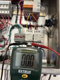
In all your pictures where you are measuring voltage, none of the SSR LEDs are lit up. You are just measuring the leakage current. It will read wall volts but minimal amps, once you put a load on it, should zero out. Is your touch screen calling for an element to be on? Are your temp probes plugged in? Usually there will be some form of safeguard to prevent the control signal from going out if there is no valid temp signal.
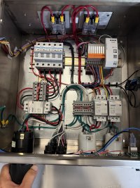
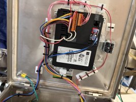
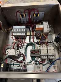
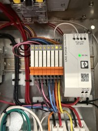
Thanks for the responses. I recently purchased the 360 controller from Ryan at Electric Brewing Supply. There were no manuals and limited guides on the web site. He has been making them for years and supplying some of the bigger breweries and Spike brewing. He has since gotten away from building them. I reached out to him to see if I had the right settings as the elements were not heating up. When I toggle the HLT output, the light on the relay group there by the Phoenix power supply turns on corresponding with the left contactor. Now my issue is the SSR’s are not turning on. (I connected a 9v battery and they turned on) I have messed with the screen setup and still no luck.
https://ebrewsupply.com/collections/360
https://ebrewsupply.com/collections/360
Attachments
Last edited:
Indian_villager
Well-Known Member
So reading more into it and with your panel shots, you don't have something that just runs standard discrete PIDs you have a whole PLC running custom software. You have a bit more info on which configuration you specifically ordered?Thanks for the responses. I recently purchased the 360 controller from Ryan at Electric Brewing Supply. There were no manuals and limited guides on the web site. He has been making them for years and supplying some of the bigger breweries and Spike brewing. He has since gotten away from building them. I reached out to him to see if I had the right settings as the elements were not heating up. When I toggle the HLT output, the light on the relay group there by the Phoenix power supply turns on corresponding with the left contactor. Now my issue is the SSR’s are not turning on. (I connected a 9v battery and they turned on) I have messed with the screen setup and still no luck.
https://ebrewsupply.com/collections/360
https://ebrewsupply.com/pages/help?hcUrl=/en-US/meet-your-new-control-screen-main-screen-506373
- Joined
- Oct 6, 2017
- Messages
- 1,708
Doing some digging, I'd guess Electric Brewing Supply is on its way out. No panels are available, just a limited set of parts. They are building the building out as an AirBNB and Ryan lists 3 jobs on his LinkedIn including the AirBNB and a full time job at regional brewery.
Thanks for the responses. I recently purchased the 360 controller from Ryan at Electric Brewing Supply. There were no manuals and limited guides on the web site. He has been making them for years and supplying some of the bigger breweries and Spike brewing. He has since gotten away from building them. I reached out to him to see if I had the right settings as the elements were not heating up. When I toggle the HLT output, the light on the relay group there by the Phoenix power supply turns on corresponding with the left contactor. Now my issue is the SSR’s are not turning on. (I connected a 9v battery and they turned on) I have messed with the screen setup and still no luck.
https://ebrewsupply.com/collections/360
I'm pretty confident this is just the result of a steep learning curve. You have a controller that has custom and customizable software installed. It will put out the correct DC voltage to the SSRs when the software tells it to. Aside from actually being supported by the vendor or someone that has experience with that actual product, there's not much we can do based on still images. Maybe take a video showing all the steps you're taking to try to fire up the elements. Something on the screen may jump out at us.
When I received the controller it was setup for Standard: 14-30 power inlet, I wanted the ability to run two elements at the same time (Double batch) so Ryan said all I had to do is change out the power inlet to a 14-50 inlet, which I did.
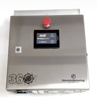
Here is the link to the controller. https://ebrewsupply.com/products/360-series-2-element-control-panel?variant=44223544721650
Panel Specifications
| 360 Controller Screen | 4.3" or 7" Horner Automations Touch Controller |
| Full load amperage: | Standard: 25.3 amps @ 240v Double Batch: 47 amps @ 240v |
| Max Output: | Standard: (1) 5500w Elements (240v 1ph) Double Batch: (2) 5500w Elements (240v 1ph) (2) Brewery Pumps @ 1.2 amps |
| Power outlet: | Standard: 14-30 Dryer style Double Batch: 14-50 Range style |
| Power cord: | Standard: 6 foot molded cord with L14-30 connector Double Batch: 6 foot molded cord with CS6364C connector |
| Power in: | L14-30 Flanged inlet, 240v with ground and neutral. CS6375 Flanged inlet 240v with ground and neutral. Panel uses the available 120v for control and pumps International, 220v variance available |
| Panel outputs: | (2) L6-30 flanged outlets for elements (2) Neutrik 120v Power-Con outlets for pumps (4) Neutrik 120v Power-Con outlets for fermentation |
| Panel inputs: | (4) XLR inputs with M12 variant cables for NPT and TC probes (1) Cat5 network port for net communications (1) Cat5 Cscan expansion communications port |
| Enclosure: | Stainless Steel Nema 4x Enclosure 15 in (W) x 15 in (H) x 8.5 in (D) 380mm x 380mm x 215mm |
| Input probe type: | RTD / PT100 |
| Included in the box: | (1) Control Panel (1) Power cord for panel (3) Temp probe cables (X) Temp probes dependent on selection |
| Certifications: | Controller is not certified UL |
| Point of origin: | Enclosure from Ohio, USA Touch control from Indianapolis, IN, USA Terminal blocks, relays and power from Germany Outlets and inlet, contactors, breakers and SSRs from China |
| Warranty: | 1 year parts, 90 days labor |
Indian_villager
Well-Known Member
Dumb question, that big honking e-stop isn't pushed in right? It has been reset by twisting in the direction indicated?
When it is pressed it shows on the screenDumb question, that big honking e-stop isn't pushed in right? It has been reset by twisting in the direction indicated?
Attachments
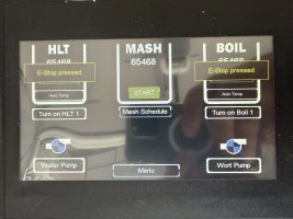
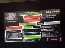
One question, why are all the "controllers" reading a 65,468F temperature?

In other product photos, it's clear the top number is the actual value and the lower number is the set value:

When you changed the input plug to 50 amp, did you go into the setup and set it for back to back instead of interlock?
In other product photos, it's clear the top number is the actual value and the lower number is the set value:
When you changed the input plug to 50 amp, did you go into the setup and set it for back to back instead of interlock?
- Joined
- Dec 13, 2012
- Messages
- 89
Doing some digging, I'd guess Electric Brewing Supply is on its way out. No panels are available, just a limited set of parts. They are building the building out as an AirBNB and Ryan lists 3 jobs on his LinkedIn including the AirBNB and a full time job at regional brewery.
Looks that way. I E-mailed Ryan a week ago,
Hi Ryan,
Thanks for the quick turnaround on my order.
Looks like you're getting out of the brewing control panel business. Any brewing-related plans for the future?
Joe
I haven't heard back. I had ordered (and received) a few spare PIDs and a timer.
I also noticed that Spike is bundling the 15G, 20G and 30G Trio System with what appears to be a pair of Solo Panels, rather than the rebranded Electric Brewing Supply Panel. The 50G Trio System is bundled with FOUR Solo Panels. Holy cow! The Nano System is still depicted with a rebranded Electric Brewing Supply Panel, however, it's listed as "Sold Out". Not sure if that's still being offered. Not sure what came first ... Ryan exiting the brewing control panel business or Ben opting to incorporate his own Solo Panel.
I have a couple thousand dollars wrapped up in a custom Electric Brewing Supply four-PID 3-element RIMS Control Panel. I have my fingers crossed that I'll get several more years of trouble-free use out of it.
- Joined
- Oct 6, 2017
- Messages
- 1,708
FYI, you can swap the Electric Brewing PID for an EZBoil in about 10 minutes.
I ordered a spare temp cable, everything else is something that can be purchased off the shelf. Could always make a cable but having one pre-made is a lot easier, and not much more expensive. Bigger concern for me was that the wiring diagrams are not accessible. I found I could still get them from archive.org so I grabbed them and saved copies away.
Shame to see them going away. I was really interested in a 360 panel but wanted to do some integration to it, they really weren't interested in letting me do that.
I like most of their products but that is obnoxious. I get it, it was the fastest way to continue supporting the system builds but switching a second element off the same controller is as simple as building an aux relay box like Blichmann did on their brew commanders.
Last edited:
The good news is that everything in the older panels is industry standard and doesn't rely on eBrew or Spike staying in business. Even if you prefer the PIDs that came in that panel, they're not even an exclusive eBS product. I'd put the Auber DSPR120 and/or the 320 in there proactively anyway.I have a couple thousand dollars wrapped up in a custom Electric Brewing Supply four-PID 3-element RIMS Control Panel. I have my fingers crossed that I'll get several more years of trouble-free use out of it.
- Joined
- Dec 13, 2012
- Messages
- 89
FYI, you can swap the Electric Brewing PID for an EZBoil in about 10 minutes.
My OCD would flare up if the replacement PID didn't match.
I ordered a spare temp cable, everything else is something that can be purchased off the shelf. Could always make a cable but having one pre-made is a lot easier, and not much more expensive. Bigger concern for me was that the wiring diagrams are not accessible. I found I could still get them from archive.org so I grabbed them and saved copies away.
I replaced all four of my Electric Brewing Supply cables with custom-length cables from The Electric Brewery. The Electric Brewing Supply cables are manufactured and assembled in China and are about as cheap as you can get. The Electric Brewery cables are really nice. I plan to use the Electric Brewing Supply cables with a four-PID counter-flow wort chiller digital thermometer, however, if that project goes well, I'll likely end up replacing them with cables from The Electric Brewery as well.
Shame to see them going away. I was really interested in a 360 panel but wanted to do some integration to it, they really weren't interested in letting me do that.
I agree. At the time I purchased my custom four-PID 3-element RIMS Control Panel from Ryan, I looked and looked and looked at the 360 Series, however, I knew that I'd want to modify the Horner controller programming. I'd spend all my time mucking with the control panel rather than brewing.
Hopefully, Kal at The Electric Brewery will pick up the slack.
- Joined
- Dec 13, 2012
- Messages
- 89
I like most of their products but that is obnoxious. I get it, it was the fastest way to continue supporting the system builds but switching a second element off the same controller is as simple as building an aux relay box like Blichmann did on their brew commanders.
Electronics have never been Spike's strong suit. They rebrand a $30 Inkbird (after having disabled your ability to modify the temperature differential) and resell it for $80.
Indian_villager
Well-Known Member
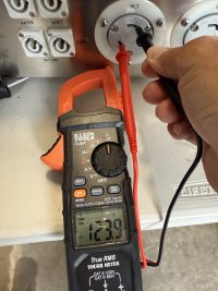
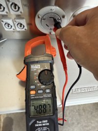
In his other pics where he is testing voltage out of the L6-30 plugs the temps seem realistic. I'm leaning toward he had the temp probes unplugged when doing the e-stop test. Looks like they didn't cap the scale or put in open loop detection. This is made all the more frustrating that there is no documentation on this available on their site, and their youtube channel only has a video telling you how to update the firmware.One question, why are all the "controllers" reading a 65,468F temperature?
View attachment 885376
In other product photos, it's clear the top number is the actual value and the lower number is the set value:
View attachment 885377
When you changed the input plug to 50 amp, did you go into the setup and set it for back to back instead of interlock?
Hey @lmr275rgr can you try selecting that "back to back brewing" button and deselect 1/2 element? Make sure to have your temp probes plugged in while testing.
Right. Back to back is the 50amp mode for sure. The software seems to have an element enable function (which you verified pulls in the contactor to allow voltage to go to the element cord) but the controller also needs to have the set point temperature above the actual probe reading temperature for the controller to output SSR control voltage. Both of those have to be satisfied at the same time.
Similar threads
- Replies
- 20
- Views
- 2K
- Replies
- 4
- Views
- 2K
