OP
OP
nostalgia
Well-Known Member
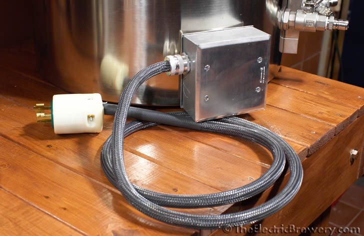
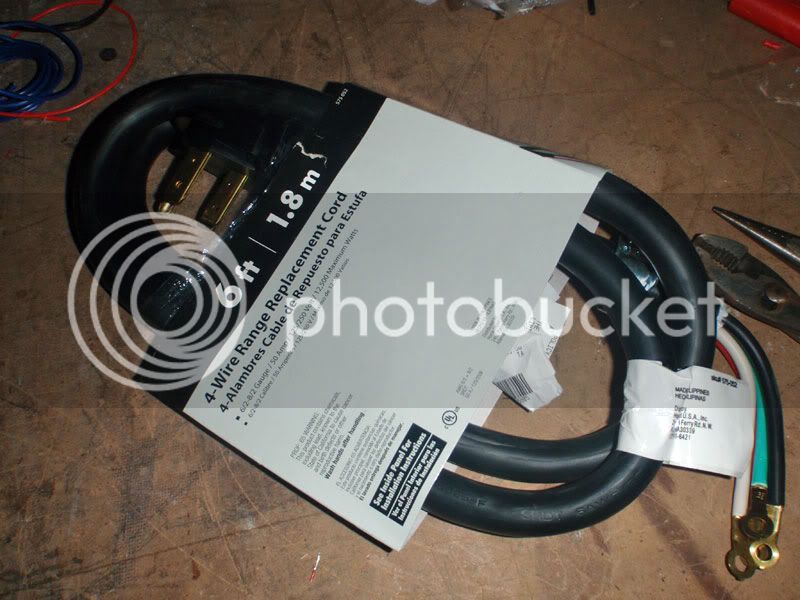
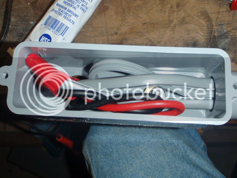
Finally found a 50A appliance cord at my local Home Depot. I was going to use the Romex-style stuff for initial testing but it's so damn stiff. The appliance cord was a lot easier and neater to wire, too, which makes me happy.
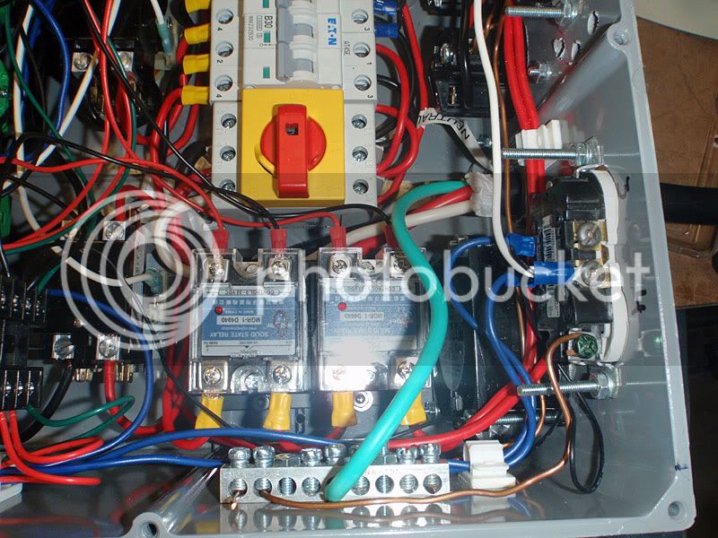
Broke out the continuity tester for some final double-checking. Good thing I did - I had the PIDs wired to the wrong SSRs. Then it was time to plug it in. The butterflies start...
Flip the big switch on the control panel and...hmmmmmmmmmm the cooling fan is running! And moving a *ton* of air.
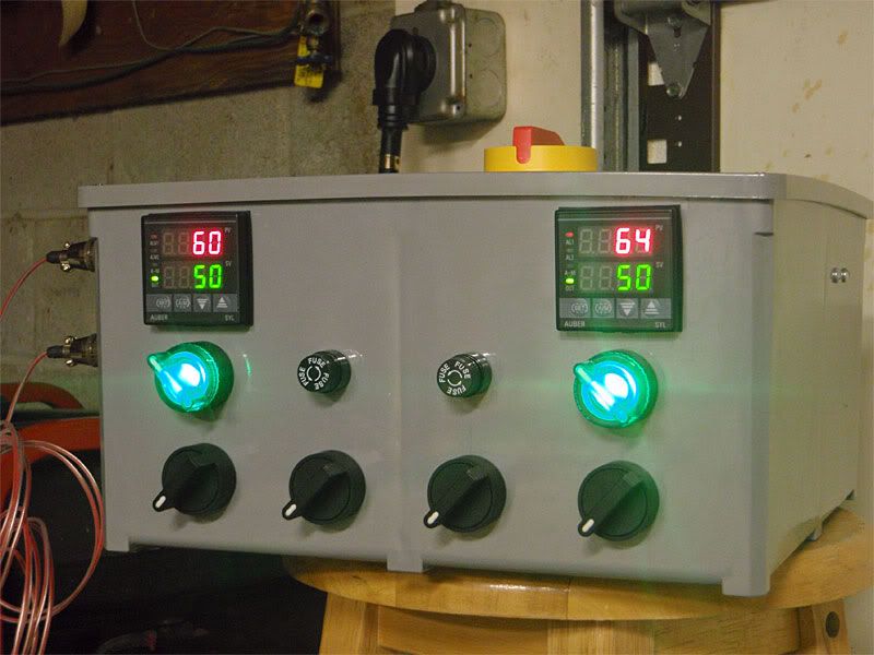
Wooooooooooooooooooooooooooo! Interestingly, the RTDs are 4 degrees off from one another. I'll have to figure out how to fix that. I should have switched them to see if it's the RTD or the wiring inside.
I checked all of the switches and all 4 of the 120v outlets. Everything is wired correctly and works as intended.
So yeah. Exciting! Celebratory Scotch time! Laphroaig, here I come.
-Joe
Broke out the continuity tester for some final double-checking. Good thing I did - I had the PIDs wired to the wrong SSRs. Then it was time to plug it in. The butterflies start...
Flip the big switch on the control panel and...hmmmmmmmmmm the cooling fan is running! And moving a *ton* of air.
Wooooooooooooooooooooooooooo! Interestingly, the RTDs are 4 degrees off from one another. I'll have to figure out how to fix that. I should have switched them to see if it's the RTD or the wiring inside.
I checked all of the switches and all 4 of the 120v outlets. Everything is wired correctly and works as intended.
So yeah. Exciting! Celebratory Scotch time! Laphroaig, here I come.
-Joe


![Craft A Brew - Safale BE-256 Yeast - Fermentis - Belgian Ale Dry Yeast - For Belgian & Strong Ales - Ingredients for Home Brewing - Beer Making Supplies - [3 Pack]](https://m.media-amazon.com/images/I/51bcKEwQmWL._SL500_.jpg)


")