Dual Element 5 Gallon Batch 120V Build

Homebrew Talk - Beer, Wine, Mead, & Cider Brewing Discussion Forum

Help Support Homebrew Talk - Beer, Wine, Mead, & Cider Brewing Discussion Forum:

This site may earn a commission from merchant affiliate links, including eBay, Amazon, and others.

Jeebas

Supporting Member
HBT Supporter
Joined
Mar 16, 2010
Messages
474
Reaction score
42
Location
Pittsburgh
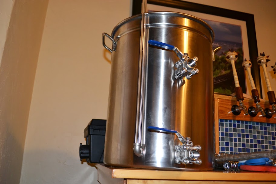
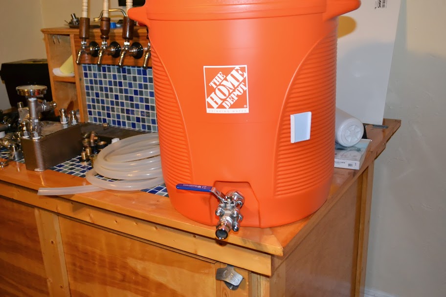
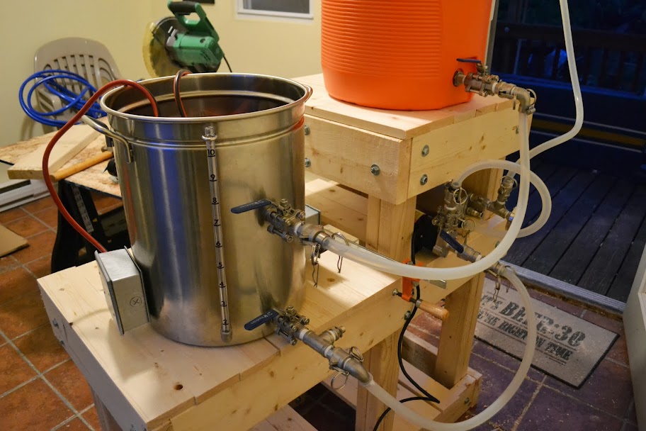
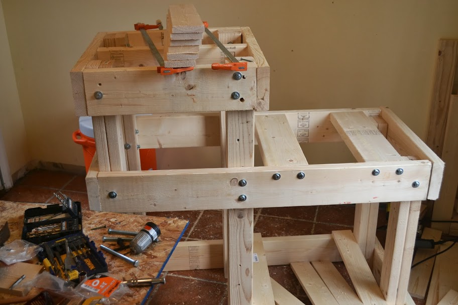
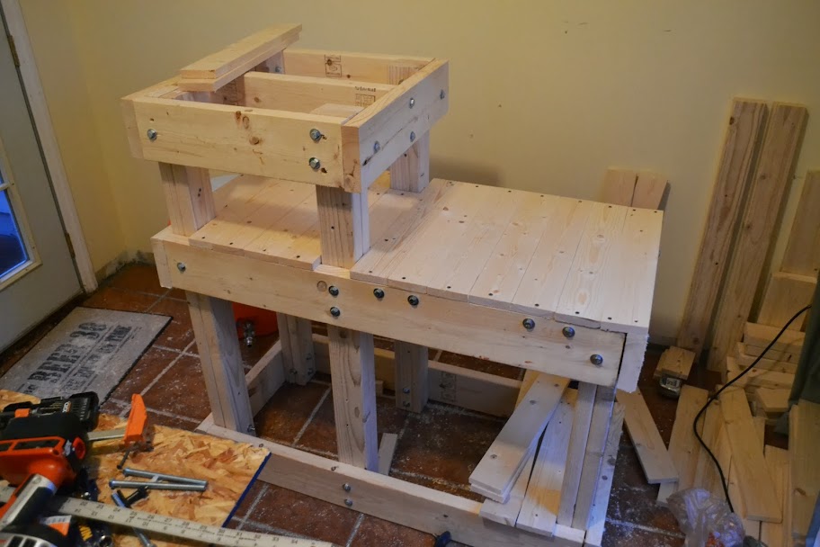
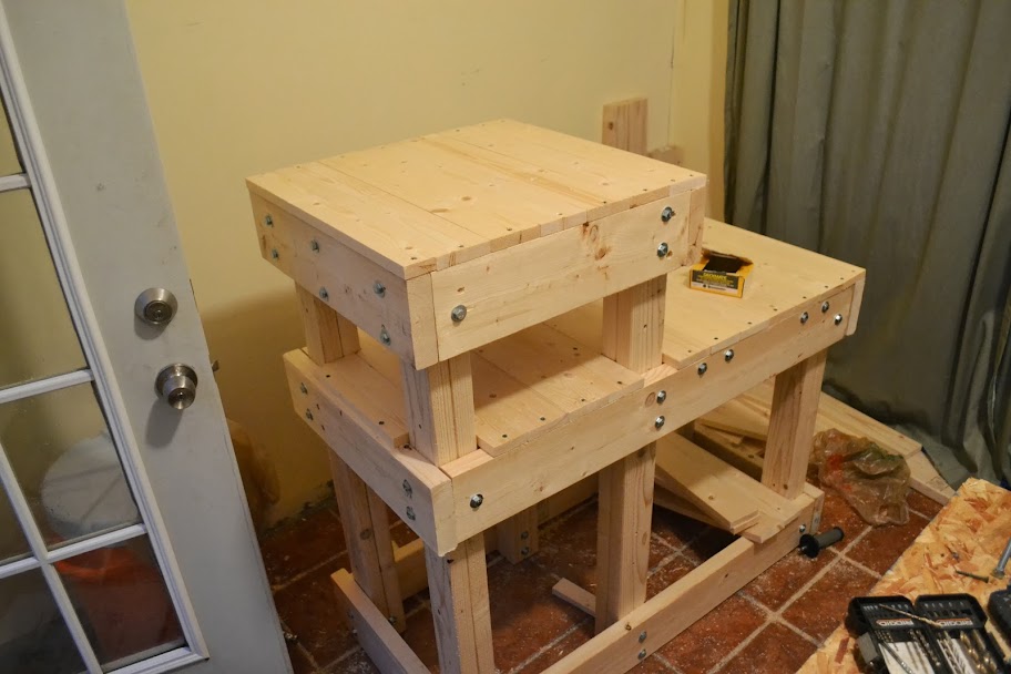
This thread will be to document my electric brewing build. I am aiming for a variant on jkarp's CB20 build. Some changes to the design will be that I am going to use a plate chiller instead of a CFC (I plan on using a hop spider in conjunction with a kettle screen to minimize any blockage - I used these and had no problem in my last build that was constantly recirculating), a 11 gallon pot and a 10 gallon cooler. I want to do 5 gallon batches so I will be using two 120V elements, one controlled by a PID and the other just plugged in (to use during the boil). I also plan on making a wood stand in lieu of the cooler sitting on top of a bucket. I already found two separate 20A circuits in my kitchen so I should be good in that regard.

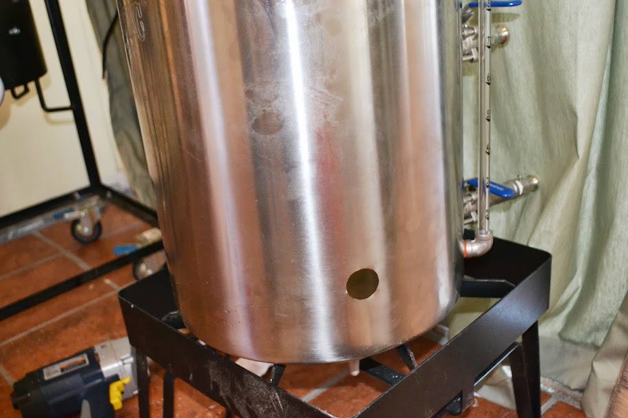
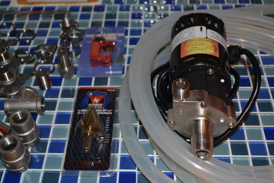
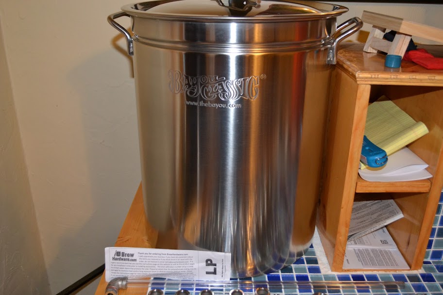
I have sold some of my old setup and just put in my first order on Amazon and BrewHardware to get my kettle, fittings, pump, hoses and some other pieces and plan on getting a cooler from HomeDepot in the next few days. Its definitely going to be a WIP for a while as I am trying to limit my funds to what I get from selling my old gear. But I hope to be brewing on it by September-October.
 
Just got my big order from BrewHardware today - everything came as ordered!

Picked up a 10 gallon cooler last night and got my 44 quart bayou pot last night.

I am gonna assemble stuff as I go. Hoping to take some pics of all of the parts laid out tonight.

I am still up in the air on which FB to go with, as I already have the valve and bulkhead for the MLT out. Not sure if I want to go with the ones that sit ABOVE the valve or the ones that sit below it and require 90 degree barb fitting -> tubing -> hose barb to connect to the MLT output.
 
I'm hoping to start building an electric HLT off 120V soon, I'll be looking forward to your build!
 
Looks like you're off to a good start! i have the same basic concept as well with 2 keggles. works epicly!

good luck!
 
It is exactly what I was looking for. I want to do the same with my setup but use propane with an heating element to boil then just use the element to keep it rolling by itself. I want to do this to cut costs on propane. I'm looking forward to your future updates.
 
Here are some pics of the fittings, sight glass, some tools, high temp silicone hose, center-inlet chugger pump and the as-of-yet-unmodified 44-quart Bayou Classic pot.

I picked up some rolls of teflon tape today and hope to install the kettle fittings and sight glass tonight and maybe get some hoses put together.

DSC_0816.JPG

DSC_0817.JPG

DSC_0820.JPG

DSC_0823.JPG

DSC_0824.JPG

DSC_0825.JPG
 
Cool. I plan on doing the same thing soon. I look forward to your updates.
 
I made some progress over the weekend.

I drilled all of the holes in my pot, with the exception of the holes that I am going to need for the elements. Leak tested all of the fittings, and with some fine tuning with the bottom bulkhead, got all of them adjusted. Even though I accidentally drilled the hole for the sight glass too big (5/8" instead of 9/16") it still seals and did not have any leak problems.

I did a normal bulkhead for the drain, and will be modifying a kettlescreen (I need to fold it back / roll it up, it is just a little too long) that I already had to fit inside the pot, but I want to wait until I get the elements installed first.

I have a high flow elbow barb on the recirculation / whirlpool port, I did this installation higher than I had initially wanted but I didn't want the two valves to close together. I will likely attach a short length of tubing to the end of it so it returns the flow under the liquid level.

I did a variable length bulkhead for the cooler outlet, and this took some fine tuning to get a good seal, likely because of the plastic giving a bit more than I would have liked. I have another variable length bulkhead on the top of the cooler lid to return water to the mash during recirculation. Drilling this hole was much easier than drilling the holes in the pot :p
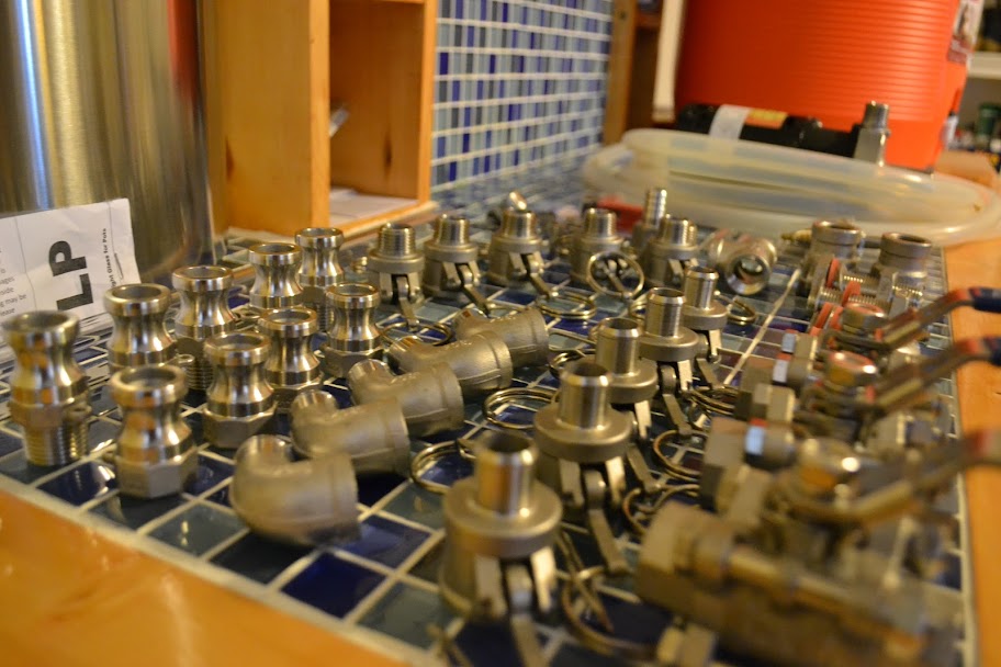
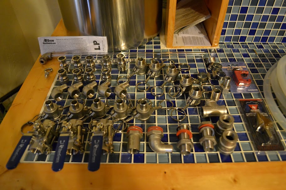
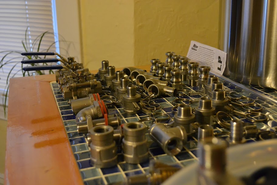
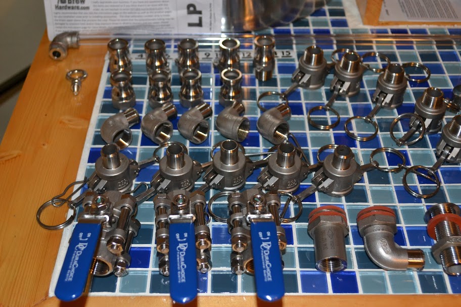
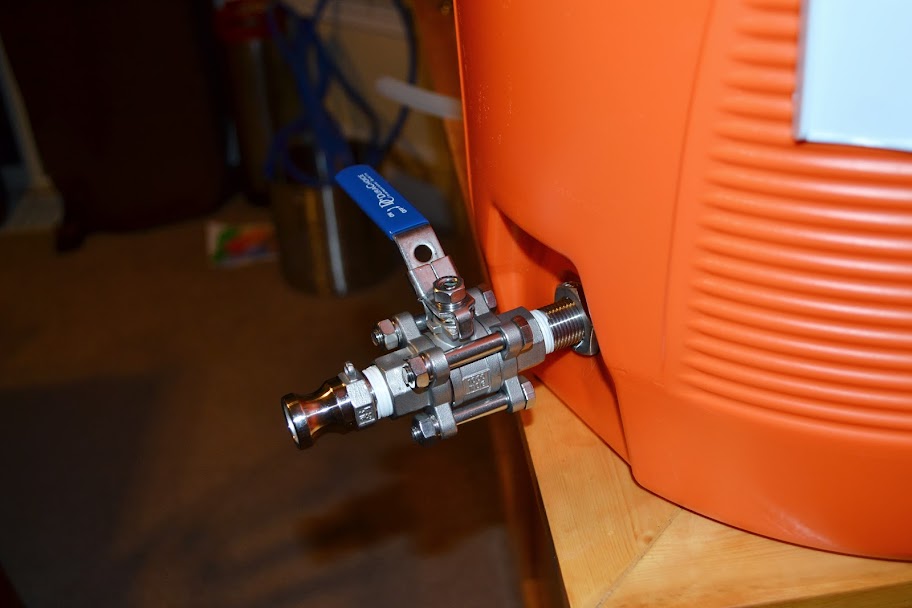
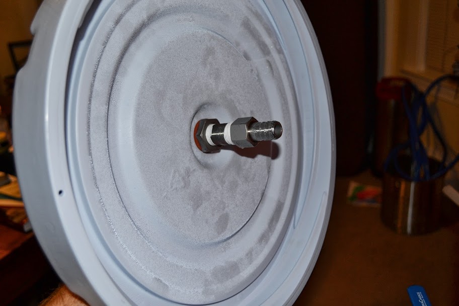
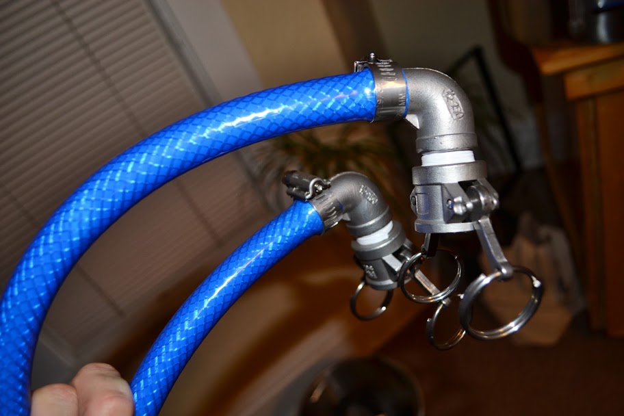
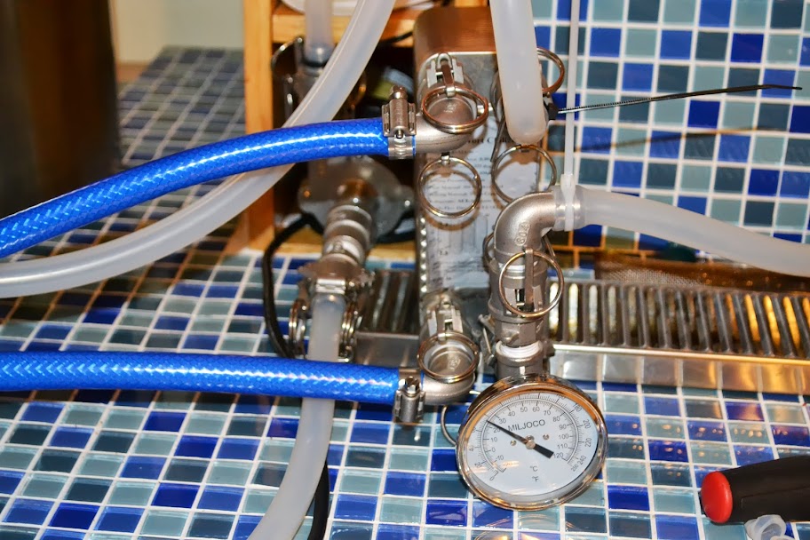
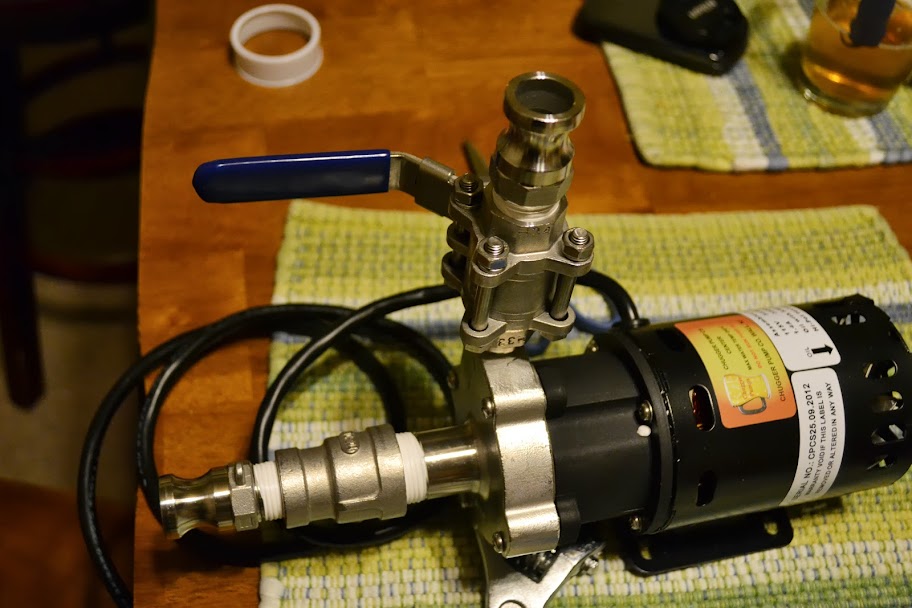
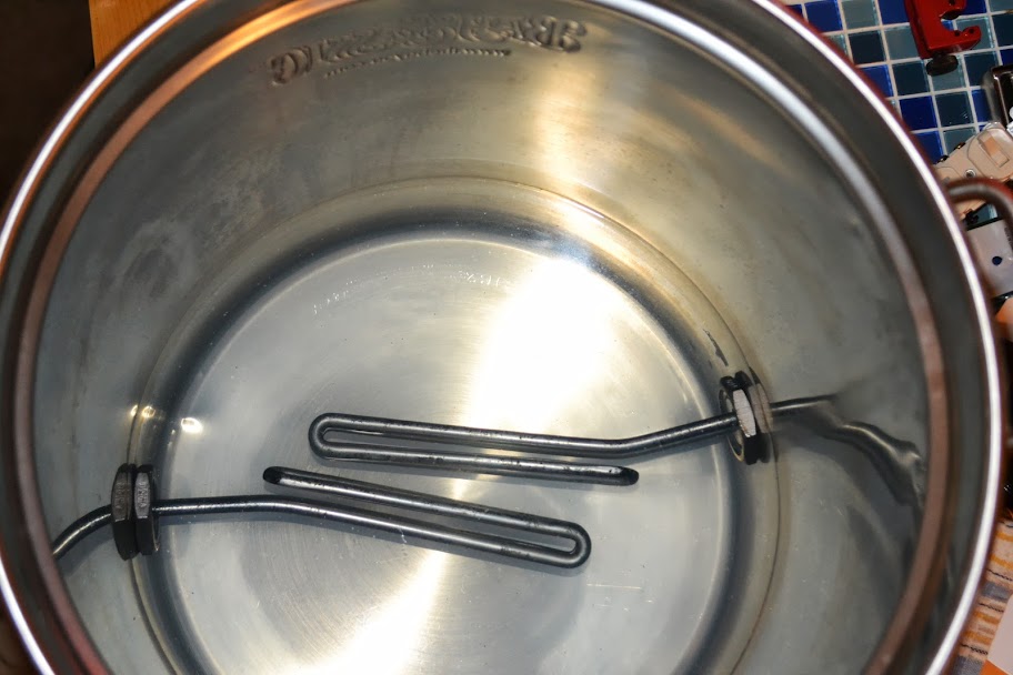
. This is probably the only place on the build that I will use a normal ol' hose barb.

I refitted my plate chiller with camlock As for both wort and water sides. Notice the difference between camlocks on the water (left) and wort (right) sides. The water-side ones were repurposed from my old build, so I am not sure if it is difference in make of camlocks from last year to this year or what. Needless to say I put the repurposed ones on the water side becasue of the smaller ID of the opening as I didn't want to cause any slowdowns on the worst side if everything else was using the newer, larger-ID fittings. Maybe it matters, maybe it doesn't :p I already had the camlock B-> tee -> thermo from my old setup as well.

I put the 3/4" -> 1/2" reducer and a camlock on the input for the Chugger pump, I didn't do anything for the outlet yet as I realized that I forgot to factor in / order another valve -> Camlock F for that. Thankfully the vendor that I am getting the locknuts for the elements from carries valves and camlocks as well.

Lastly, I cut my 25' drinking water hose in half and put high flow elbow barb -> camlock Bs on 1 side of each of them. Getting the hose onto these barbs took more work than I thought, but this hose is likely more rigid than the silicone tubing for the wort will be.

DSC_0009.JPG

DSC_0010.JPG

DSC_0011.JPG

DSC_0012.JPG

DSC_0013.JPG

DSC_0015.JPG

DSC_0016.JPG

DSC_0017.JPG

DSC_0018.JPG
 
I made some more progress this week!

I set up my system on my kegerator in more or less the way it will eventually be when I build a stand for it (and put it in the kitchen). I then measured the tubing lengths allowing for some slack (but not too much). I attached female camlocks to the end of the hoses (some were straight and some were elbows, my reasoning on this is that I wanted elbows coming out of vessels and anywhere else that it made sense) and used the two remaining SS hose clamps that came with the Add A Pump kit (I had used the other two on my water hoses) and then cable ties on any other hoses.

The wort flow will be much like the original CB20 - wort will go from the pot to the pump to the chiller, then up to the top of the cooler, and back out the cooler to the recirculation / whirlpool port of the pot.

I calibrated my sight glass following the process outlined in this video - - Its funny to see how much more space there is between numbers with a narrower pot (my old system was short wide 15G pots). Once calibrated I applied the decals and reinstalled the sight glass.

I got my water heater elements in, the nut + washer to install them and the rest of the fittings for my pump outlet as well.

I am waiting on delivery of my Auber Instruments haul, which USPS tells me should be today. I made another trip to Home Depot for some of the things needed for the water heater element installationg and wiring (I plan on following the instructions from The Electric Brewery here - http://theelectricbrewery.com/heating-elements), and hope to drill the holes for and install my elements / element boxes over the weekend.

DSC_0021.JPG

DSC_0022.JPG

DSC_0023.JPG

DSC_0025.JPG

DSC_0026.JPG

DSC_0029.JPG

DSC_0030.JPG

DSC_0032.JPG

DSC_0036.JPG
 
Last edited by a moderator:
I made a lot of progress over the last two weekends. As I said before, I followed the instructions here - http://theelectricbrewery.com/heating-elements - for installing the water heater elements.

Last weekend I marked up the holes for the various parts of the control box and pot, cut / drilled said holes, and started painting the control box and elements boxes during the week.

The hole for the PID was too large so I added some JB Weld and filed the excess down. The holes for the outlets were rough looking but will be covered with an outlet plate anyways. The "notch" for the heat sink also was cut a little sloppy, so I did more JB Weld cleanup :)

I painted the element boxes painted silver to (somewhat) match the pot. I should have waited until I put the boxes together to paint these. I painted the control box black because it looks slick, but really to cover up my mistakes :p

DSC_0037.JPG

DSC_0038.JPG

DSC_0039.JPG

DSC_0040.JPG

DSC_0041.JPG

DSC_0042.JPG

DSC_0051.JPG

DSC_0052.JPG

DSC_0053.JPG

DSC_0054.JPG

DSC_0057.JPG
 
While I was drilling one of the holes for the water heater elements, the step bit jumped on me, so it came out a bit rough, so I hammered it a bit and filed it a bit and crossed my fingers :( I think if I had to do it all over again, I would take the $80 hit for the Greenlee Punch instead of using a step bit, which is more prone to user error.

I ran into quite a number of leaks with the element box installation, but once I tightened them to the point where the element boxes were "unable to move or spin" (as suggested by The Electric Brewery) they were leak free - they held (initially very hot) water for over 24 hours with no leaks. There was a HUGE feeling of relief over the one poorly drilled hole when I didn't see a leak after a few hours. I slowly bent the elements over a 2x4 so that they wouldn't touch each other when installed.

I have the control box all laid out - The heat sink just slides into the notch, and the PID fits perfectly into the hole for it now. The panel mount for the RTD probe did have a locknut, it just assumed that the panel would be of a thinner material, JB Weld to the rescue again! I may have to do the same for the cord grip, but it seems pretty secure as of now.

DSC_0055.JPG

DSC_0056.JPG

DSC_0058.JPG

DSC_0063.JPG

DSC_0064.JPG

DSC_0065.JPG

DSC_0066.JPG

DSC_0067.JPG


Still remaining I need to:
* Silicone the water heater elements
* Wire the element boxes and close them up
* Wire the control box
* Acquire a false bottom
* Construct a rough 2x4 "sculpture" that I can attach the pump (its too top heavy otherwise) to and mount the plate chiller to.

I eventually want to build a stand / cart, but I need more $ and need input from my better half on that, and with a beach vacation coming up soon and a pretty big yard project right after that, discussing me taking over the kitchen is not at the top of the priority list. For the time being, I can just move the microwave off of our island when I want to brew.
 
Do you have a closeup of that hole?? It looks just fine :) if all else fails, soldering a spud will do fine if all else fails, or 2 washers to beef it up
 
Thanks for all the kind words, everyone!

So I am more or less done with the build, I siliconed the elements, wired the control box and wired the elements last week. Yesterday I managed to test out the elements - I tested each one individually and then tested both (plugged into outlets on 20A circuits of course) taking 4 gallons (I will have more in the pot when actually brewing but didn't feel like filling it all the way to the brim) up to boiling.

* I did not electrocute myself!
* I didn't trip any breakers!
* There were no leaks!

I used the wiring diagram here https://www.homebrewtalk.com/f170/step-step-build-110v-portable-pid-controller-379938/#post4764563 as a guide, but added another switch outlet combo to control the pump.

Lessons learned:

1) Spade terminals are needed for 12 gauge wire going into plugs.
2) 12 gauge wire will not fit into the PID terminals
3) You need way more than 15 feet of cable to have spare for the wiring inside the box and to have reasonable lengths for the control box power cord and two element cords.
4) Removing the transparent shell on top of the SSR makes wiring those terminals MUCH easier.

I will post some photos in the next day or so.
 
I ran auto-tune last night on my PID. It worked... for the most part. I exposed some poor wiring work on one of my plugs - the 12 gauge wire came out of one of the spade terminals when I was pulling a cord out of the socket. Likely the larger problem was that I didn't have the plugs cord grip screwed down tight enough and it pulled the wire right out. In any event, I plugged the other element in and just used that.

An "issue" with my design is that the RTD probe is located in the tee, beyond the valve. So anytime I want to get any kind of reading on the temp, I have to be recirculating. Its not really an issue as I plan to recirculate most of the time.

I started auto-tune and I had my system plumbed like in the picture below (I have newer pictures, they are just still on my camera)

DSC_0026.JPG


From the pot to the pump to the chiller, then up to the top of the cooler, and back out the cooler to the recirculation / whirlpool port of the pot.

Then I realized that I really didn't need to have the mash tun hooked up, so I took it out of the "flow" (hooked up the chiller out to the pot whirlpool ineatsd of the the MLT recirculation port) and turned off the main power to the PID and then restarted the auto-tune. Unless I missed it, the auto-tune mode never reached the SV that I had of 154, it got to 146 and then went out of auto-tune mode. I let it run and get up to 157, and then ran auto-tune again, with the SV still at 154. Auto-tune mode ran until it drops to 152, then turned off. Reading the manual I thought that auto-tune was supposed to go heat up to the SV and fall back down from it like 3 times. I then realized that I had the "intY" set to p100 instead of p10.0, but I am not sure why that would affect auto-tune.

I have the SYL-2362 - some of the other settings that I changed were:
I set the FILT to 3 (initially 0)
Is set the HY to 1 (initially 3)

I will probably just run auto-tune again, but I was wondering if anyone had experienced this before or had any ideas.
 
As far as a brewday, I will probably be doing this -

#1 Heating strike water - Pot -> pump -> chiller -> pot
#2 As the strike water approaches strike temp (adjusted up for transfer loss), start to recirculate it - So turn the pump off, move the chiller out to the MLT recirculation port, and hook the MLT out hoses to the pot whirlpool port - in order to "pre-heat" the MLT. Turn the pump back on
#3 Once the temp is reached, close the MLT out valve and let it fill to my desired infusion level. Turn off pump.
#4 Dough in.
#5 Calculate balance of water needed to meet desired pre-boil volume. Hook up chiller out back to the pot whirlpool port. Turn on pump. Set PID to mashout temp.
#6 Mash complete. Turn off pump. Hook up chiller out back to the MLT recirc, MLT out back to the pot whirlpool.
#7 Turn on pump. Recirculate for 30 minutes.
#8 Let all wort fall back into the pot. Turn PID to manual mode. Close all valves.
#9 Normal boil stuff - no recirculating of any kind going on.
#10 Towards end of boil, hook up chiller out back to the pot whirlpool port. Recirculate to sterilize chiller.
#11 While sterilizing, attach the water hoses to the chiller.
#12 Chill.
#13 Transfer to fermenter.
#14 Clean.

If this sounds a lot like https://www.homebrewtalk.com/f51/countertop-brutus-20-a-131411/index4.html#post1481940 its because I was basically writing that out for myself and adding / omitting what I needed / didn't need. It helped me understand the process better.
 
Jeebas,

Nice job on the build. I am looking to do the same for a converted Keggle with two elements for an eHLT. I have a plug and forget setup now with one 2000W element in an 8gal pot that use to heat mash and sparge water. I just have to baby sit it to keep from overshooting the mash temp.

One thing I cannot wrap my head around with a two element set up is if I run a 2000W and a 1500W element off of one PID I can't see how the power could come from one source (i.e. one 20amp outlet). Are both elements not on at the same time or does the PID and SSR handle the increased amp requirement?

Or am I just overthinking it?.

When I do the boil, I plan on switching the PID controlled element to manual mode and then plugging the other element into a separate 20A circuit "plug and forget" style. Hope that helps.
 
Here are some pics of my testing the other night

One of the water heater elements wired up

DSC_0115.JPG


Me trying to figure out how to program some parameters into the PID

DSC_0120.JPG


The system all set up and running

DSC_0122.JPG


PID in auto-tune mode

DSC_0123.JPG


It's ALIVE!

DSC_0127.JPG
 
It has been a while since my last update - vacation and other various things took up a lot of my time (which isn't a bad thing). Here are some pics of the progress over the last two weeks, mainly dealing with the building of the brew stand / cart.

Materials for the brew stand/cart all laid out

DSC_0514.JPG


Two saw horses, some OSB, and a chopsaw = workbench

DSC_0520.JPG


The proposed framing

DSC_0521.JPG


Proposed layout of the lower level (without legs)

DSC_0535.JPG


Screwed two 2x4s together for each of the legs

DSC_0560.JPG


The top tier screwed together temporarily until I could get clamps and drill holes for the hex bolts

DSC_0561.JPG


Structure finished, 1x4s laid on top and rough layout of components double-checked

DSC_0562.JPG


The frame and all support pieces are finished

DSC_0572.JPG


1x4 shelf top pieces installed on the middle level

DSC_0573.JPG


Shelf top pieces installed on the top level

DSC_0575.JPG


I still need to finish the bottom tier. Sand. Stain. I will hopefully finish this up in the next two weeks with whatever spare time that I can find.
 
This thread is awesome. Nice work man. Look forward to seeing everything all finished up.
 
Thanks for the kind words!

I am just about to order my FB. I am pretty sure I am gonna go the JayBird route as I just have a pipe nipple coming into the inside of the cooler and don't want to bother with getting extra hardware and would rather have the FB above the spigot. I also need a street elbow for the pump outlet so that it comes out horizontally and not vertically.

Still thinking about pump and plate chiller placement, which involves keeping the pump motor shielded from spills and securing the plate chiller to the stand in a way that allows for easy removal to gravity drain it after cleaning it.
 
Apart from figuring out a permanent home for the control panel that will allow to be at workable height when brewing but stow away neatly, the brewstand is done!

Three coats of stain and three coats of polyurethane

DSC_0579.JPG


The pump / plate chiller sliding platfrom with hinged ceiling to protect the pump motor from liquid

DSC_0597.JPG


Hinged so that the pump can be removed if needed

DSC_0598.JPG


Pump / plate chiller retracted for storage

DSC_0599.JPG


Pump / plate chiller extended for use

DSC_0600.JPG


Brewstand in its storage spot next to the kegerator

DSC_0603.JPG


I am hoping to do my first brew on this system in the next few weeks!!!
 
So I finally brewed on the new system early last month. I am just getting to posting the pictures now. I did a DFH 60 min clone from BYO.

My numbers were a bit off efficiency wise, but I didn't write down specifics. Next time I will plug everything into BrewTarget and focus more on the process - this time was just about getting the maiden voyage completed.

I did learn that I could use the temp probe as an indicator of how well the chiller is working, which is really handy, and makes my T -> thermo -> camlock unnecessary ( and sellable :) )

I also learned that boilovers are very easily accomplished if you look away for a minute :p The batch is kegged and darn near carbed up, should be ready next Monday!

DSC_0606.JPG


DSC_0607.JPG


DSC_0608.JPG


DSC_0609.JPG


DSC_0611.JPG


DSC_0612.JPG


DSC_0614.JPG


There are various minor improvements that I would like to make to this, but I am satisfied enough to call it done!

For those interested about cost, I spent $1,340.63 on it for parts that I didn't have (not counting shipping or tax). I already had the plate chiller and two camlocks for it and the drinking water hose, so tacking those on brings the total cost to $1462.93. I had to buy some task-specific tools (step bit, water heater element wrench, hole saw, etc.), but they were included in the aforementioned cost. I also used various tools that I already owned - miter saw, screwdrivers, drill, socket wrenches, orbital sander, but nothing super expensive or out of the ordinary. I included all stain and staining supplies in the cost as well. If anyone would like a detailed rundown of the costs, I can get you a copy of the spreadsheet.

If I could do things different, I would definitely go the hole punch route instead of trusting the step bit to make a good hole for the heater elements. It worked out for me in the end but the extra $80 would have been worth the peace of mind.

Thanks to:

* jkarp - https://www.homebrewtalk.com/f51/countertop-brutus-20-a-131411/
* Disintegr8or - https://www.homebrewtalk.com/f170/how-build-5-gal-110v-ebiab-kettle-304914/ AND https://www.homebrewtalk.com/f170/step-step-build-110v-portable-pid-controller-379938/
* Kal Wallner / TheElectricBrewery.com - http://theelectricbrewery.com/heating-elements
* Bobby_M / BrewHardware.com
* Everyone who everyone who answered any of my questions about electric brewing, or building stuff or brewing in general.
 
Looks good! Just pay attention with those hoses and minimize any wort loss and your efficiency should be fine.
 
You're not using an exhaust hood ? Did you have any problems with moisture during the boil ? That's a lot of steam escaping the pot
 
You're not using an exhaust hood ? Did you have any problems with moisture during the boil ? That's a lot of steam escaping the pot

Nope. You can't see them in the pictures but there is a ceiling fan directly above where it was in the kitchen and a window directly across from it. It's meant to be mobile (all I need is two 20A circuits, which I have in the kitchen, but it doesn't "live" there) so installing an exhaust hood isn't really an option.
 
Haha ! Glad you saw my setup....at first my stand was like yours but i was afraid of doing damage to my mom's house because of the humidy when brewing in the basement. Anyway, when I'll have my own place, i'll need something portable and might remove my hood for a while to make it more compact like yours
 

Latest posts

Back
Top