Do I start over?

Homebrew Talk - Beer, Wine, Mead, & Cider Brewing Discussion Forum

Help Support Homebrew Talk - Beer, Wine, Mead, & Cider Brewing Discussion Forum:

This site may earn a commission from merchant affiliate links, including eBay, Amazon, and others.

wizdumb1

Well-Known Member
Joined
Jul 31, 2013
Messages
64
Reaction score
46
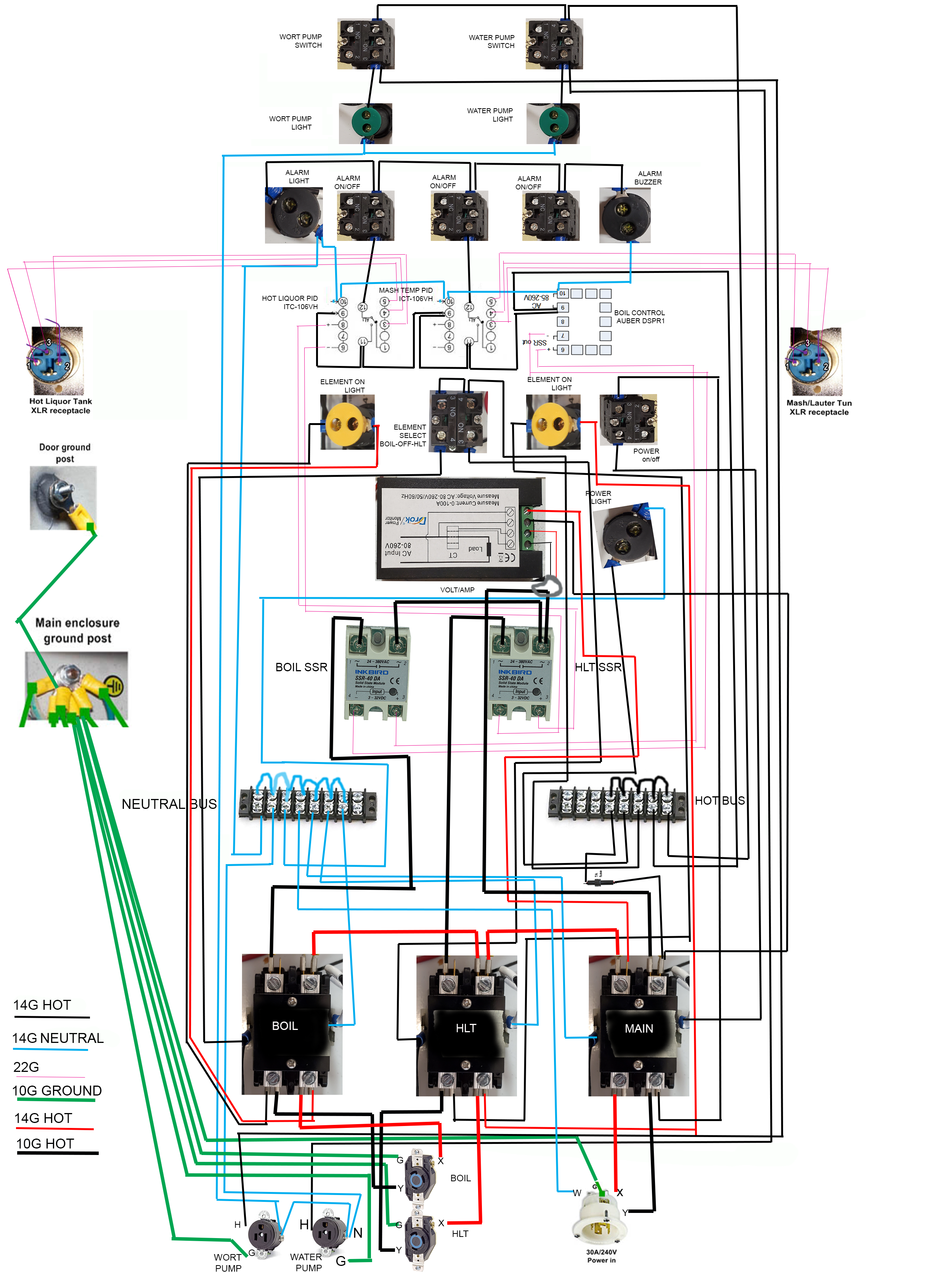
I started building a control panel a few years back and I was pretty close. Life just got in the way and to the back it went.

I finally start pulling everything out and I see a mess...lol I followed 2 different online designs. At the time I knew the basics of what was going on. I never drew out a wire plan.

Silly post I know, But now I'm wondering if I should strip it out and start over.
20200916_221731.jpg
received_807026330108894.jpeg
received_1257549504591492.jpeg


I'm so close. I just need to finish the panel, Drill some holes in my pots, and pick up random parts. Most of the big stuff has already been bought and has been sitting around waiting for years for me to look at it.
 
Personally I'd probably sit down with the list of components and draw a diagram first then go through what you've got and pull anything that doesn't meet the new diagram and redo. You might end up out a little bit of wire and some crimps but you'll probably be happier you did it "right" and certainly be happier you have a diagram if you need to troubleshoot.
 
Personally I'd probably sit down with the list of components and draw a diagram first then go through what you've got and pull anything that doesn't meet the new diagram and redo. You might end up out a little bit of wire and some crimps but you'll probably be happier you did it "right" and certainly be happier you have a diagram if you need to troubleshoot.

This is what I am thinking, I'm just torn with the idea...lol I remember the hours put into it. I feel I need to refresh my understanding of why it is set up the way it is and have a diagram in place in case things go wrong later.

I dunno, that looks like a complete and usable system right there. I'd be motivated to get it working...

Cheers!

And this is the other side of my mind. I know is there are some unfinished connections in there that I am sure of. With no notes or diagram to double check my work I don't want to risk toasting it or hurting myself. It's been a few years and I remember before I put it away I had to finish off some things but I cannot remember what....lol
 
Doesn't look like that big of a mess. Definitely not ready to roll, as there are no SSR's included yet.

I second @matt_m 's recommendation to trace all the wires to make a diagram of what is already in place. Then you can figure out what still needs to be added, or corrected. To finish up, first draw the rest of the schematic, and only then start adding the rest of the components and wires.

Brew on :mug:
 
Any recommendations on software to draw a diagram? The SSR's are in there, Just inside the top of the box. I have one wire that is simple to connect, It's just a Ground to the door and 4 wires I forgot where they went. HaHa I think those run to the SSR. And I'm unsure about the small jumper wires on the Hot and Neutral strips, It seems like they are not all in.

I think I'll start drawing for now and trace it all out. I just found the 2 sites I used to build it.

Oh my, where are the original plans/diagram?
 
I used some parts from this site, That is where I started off. But then I went to the electric brewery site and went off of that tutorial skipping past the parts I did not add. I skipped out on the timer and the safe start interlock and used a different Volt/Amp meter.
 
I sometimes think what if someone inherited my brew system with control panel and all incomplete. Would someone be able to finish it? I suppose some kind of diagram would speed things up. Just the thought of my electrician friend trying to approve(non formally) my control panel seems like a massive task.
 
Arg. I'm reading, I might be wrong, but you really have no plan.

Back when I started I don't think I had 1 solid plan in mind. I was just going to follow the electric brewery but found a version that took out parts I didn't see a need for. So in a way I guess your right, I don't have a plan. Time to make one.
 
Any recommendations on software to draw a diagram?

I used Visio - it's not ideal, but I'm used to using it for work and had it available. You could check out sketchup free version - gonna be a learning curve here, but watch a few videos to get the hang of it. One advantage to using software like either is that once you create a component for your diagram, like a switch, you can easily save it to reuse it.

So in a way I guess your right, I don't have a plan. Time to make one.

How's the planning coming along? I'm in the process of building my first panel as well and have been posting progress on this forum - which has been hugely helpful with the process.

I spent a little over a year noodling over building a panel, reading up on it here, the site you linked, The Electric Brewery and ebrewsupply. When it came down to acutally getting the project started, I began by creating a punch list of the features I wanted based on everything I'd read. From there, I reviewed a bunch of diagrams I'd collected and got down to drawing up the diagrams. Looking at your pictures, it looks like you're most of the way there - might be easier to find a diagram that has all your components, print it off and cross out the parts that aren't relevant for you. I found the diagrams from @doug293cz to be super helpful - searching this forum for his posts with 'diagram' as the search term turned up quite a few threads where he's posted diagrams.
 
I have a very similar panel and you are pretty close to being in the same boat I was. I found my panel on the FB marketplace. I bought it off a guy who put all the components together and never wired it. He had young kids I think. He was supposed to send me the instructions but never got around to it but I was pretty confident he followed the plans here. This was before I joined HB Talk and I don't know the ins and outs of the various plans but I did wire mine using the plans I linked and have been using it for over a year and a half. The only issue I have had with it was recently the Inkbird needed to be recalibrated, there's an algorithm it follows for the temperature but the instructions suck. I got it figured out by reading a different manufacturers instructions. Perhaps for an industrial user the instructions are fine or they would know how the gizmo works.
20190330_143433.jpg
 
I used Visio - it's not ideal, but I'm used to using it for work and had it available. You could check out sketchup free version - gonna be a learning curve here, but watch a few videos to get the hang of it. One advantage to using software like either is that once you create a component for your diagram, like a switch, you can easily save it to reuse it.


How's the planning coming along? I'm in the process of building my first panel as well and have been posting progress on this forum - which has been hugely helpful with the process.

I spent a little over a year noodling over building a panel, reading up on it here, the site you linked, The Electric Brewery and ebrewsupply. When it came down to acutally getting the project started, I began by creating a punch list of the features I wanted based on everything I'd read. From there, I reviewed a bunch of diagrams I'd collected and got down to drawing up the diagrams. Looking at your pictures, it looks like you're most of the way there - might be easier to find a diagram that has all your components, print it off and cross out the parts that aren't relevant for you. I found the diagrams from @doug293cz to be super helpful - searching this forum for his posts with 'diagram' as the search term turned up quite a few threads where he's posted diagrams.

I have found all of the sources I used when I built it. Doing some reading and working on a diagram to double check what I did right now. It's coming back to me as I run through the wiring. I used this to start out which you can see from the panel setup, But then I went here and added some switches, Then I used this post to wire the PIDs.

Right now I'm just using photoshop to make an easy to understand diagram. It won't be pretty but it works.
 
What looks different than the Skrilz manual in particular are the alarm switches. But I am wondering once you get it figured out is that you have an alarm switch on the boil but you only have two temperature probe connections. I personally don't know how you might get the HLT and Mash probes to work the one alarm but hypothesize you can possibly. However, I wonder whether you have an input from the boil to trigger the alarm? Shared plumbing for the pump maybe? Or what is its purpose?
 
What looks different than the Skrilz manual in particular are the alarm switches. But I am wondering once you get it figured out is that you have an alarm switch on the boil but you only have two temperature probe connections. I personally don't know how you might get the HLT and Mash probes to work the one alarm but hypothesize you can possibly. However, I wonder whether you have an input from the boil to trigger the alarm? Shared plumbing for the pump maybe? Or what is its purpose?

While finishing up my sloppy diagram I did notice that it looks like 1 of the alarm switches are useless...lol I was planning on using this. Link
 
It's Messy. Anyone care to criticize? I'm just going through it and checking the connections and cleaning it up before I get the guts to plug it in.
 

Attachments

  • Complete.png
    Complete.png
    2.1 MB · Views: 50
You might consider moving the power feed for the meter to the hot bus so it is protected by the fuse.
Also, it might be worthwhile to fuse the pumps and the controllers / meter separately. The controllers require significantly less amperage than the pumps do - I'd add a 1 amp or maybe even a 500 milliamp fuse (not actually sure how small you can get away with here) to protect just the controllers and meter.

Also, I've seen a few other panels that use panel mount fuse holders - Then you don't have to power down the entire system to replace a fuse. I suppose technically you wouldn't have to power down any panel to open it up and replace a fuse, but I'd not feel comfortable doing that. On the other hand, depending on which fuse blows, the system would probably power down anyways, so this may be a moot point.

Thanks! I will look that over. Going through the connections I found some loose ones, Glad I did the check.
 
Thanks! I will look that over. Going through the connections I found some loose ones, Glad I did the check.

Good call - I did the same before powering mine up. Also grabbed my multimeter and confirmed I had continuity from kettle itself all the way back to the ground prong on my power cable before plugging it in for the first time.
 
There is one mistake..lol The voltage/amp meter is upside down 🙃
 

Attachments

  • 20201007_192513.jpg
    20201007_192513.jpg
    850.1 KB · Views: 22
Back
Top