Gravitysucks
Well-Known Member
Thanks for the link. It looks like they just produce bare boards. They don't mount components on them so I'd still have the soldering issue.How about this: https://PCBs.io/share/zk7Px

Thanks for the link. It looks like they just produce bare boards. They don't mount components on them so I'd still have the soldering issue.How about this: https://PCBs.io/share/zk7Px
The Terragady v5 board does 8 transistor outputs already, 6 on screw terminals and 2 on pin headers, with a bonus of a spot for a buzzer, one wire temp probes, an I2C bus, AND a 12v to 5V converter (you can also power it with 5V if needed) All that and the price is ridiculously cheap compared to a custom board. It does not have LED's, but a simple and cheap 8-relay board has them, as do most SSR's.
Thanks for the link. It looks like they just produce bare boards. They don't mount components on them so I'd still have the soldering issue.
Thanks again. I may have to change my plans and go with a Terragady board but I'm thinking that since I live quite close to a local university with an electrical engineering program I might possibly be able to find a student looking to make some extra money to do the soldering for me. Can't hurt to ask and if it doesn't work out I can go the pre-built CraftbeerPi board route.Whoops, sorry. I'd agree with the other poster with terragady boards. I do have some bare versions of these, still but by the time I ordered parts to solder, found the time to solder and sent you one, you might as well just get a terragady board.
Sent you a PM. You have options for sure!Thanks again. I may have to change my plans and go with a Terragady board but I'm thinking that since I live quite close to a local university with an electrical engineering program I might possibly be able to find a student looking to make some extra money to do the soldering for me. Can't hurt to ask and if it doesn't work out I can go the pre-built CraftbeerPi board route.
If you can't get anybody to solder a board for you let me know. Check with the local Home Brew Club as well. I have a populated T4.2 board that I don't need and would be willing to part with if your plan A doesn't happen. Trouble is I live on the west coast and shipping might be a problem.Thanks again. I may have to change my plans and go with a Terragady board but I'm thinking that since I live quite close to a local university with an electrical engineering program I might possibly be able to find a student looking to make some extra money to do the soldering for me. Can't hurt to ask and if it doesn't work out I can go the pre-built CraftbeerPi board route.


![Craft A Brew - Safale S-04 Dry Yeast - Fermentis - English Ale Dry Yeast - For English and American Ales and Hard Apple Ciders - Ingredients for Home Brewing - Beer Making Supplies - [1 Pack]](https://m.media-amazon.com/images/I/41fVGNh6JfL._SL500_.jpg)


Thanks for your offer. It's great that this forum has people so willing to help out. I'm going to try and hit up the university this week although with classes out of session for the summer i'm not sure I'll get very far. The homebrew club idea is a good one too. It's nice to have options and I'm sure that something will eventually work out.If you can't get anybody to solder a board for you let me know. Check with the local Home Brew Club as well. I have a populated T4.2 board that I don't need and would be willing to part with if your plan A doesn't happen. Trouble is I live on the west coast and shipping might be a problem.
I don't think there has been any updates to 3.0 really. You want to be using the most recent "master branch". Safe for you to check for an update there. There hasn't been any updates in about 8 months - good chance you're up to date anyways.I havent updated my CBPi really since 3.0 came out or shortly after because I dont want to risk breaking what's working already, so if this is functionality that exists now and i just need to update let me know!
This panel was originally a Strangebrew Elsinore box, and I liked their "hysteresis" mode because i could tell it to do X cycles on, Y cycles off, and set the duration of those cycles. This was great for my BK as i could say 2 seconds on, 1 second off, which gave me a good boil that wasnt crazy full power non stop, which when im doing 5 gallon batches is way overkill.
How do i recreate this with plugins/addons/etc in CBPi?? Ive downloaded SimpleBrewLogic and BoilPID(i think?) but neither seems to do what i want, im not controlling my element by controlling power too it, which doesnt work? I assume its because of the way my box is wired, which isnt changing so i'd like to get back the functionality of on/off cycles to control my boil.

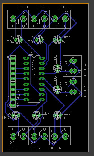
This may not be the proper place for this post but I have a question for the folks I've seen on here in the past that make CraftbeerPi boards. Do any of you do one off/ custom boards? I have a fairly simple, at least in my mind, board I've been trying to put together in order to use a ULN2803 or ULN2804 between my Pi and SSR's, etc, depending on the power supply I chose. Normally I'd do it myself put I had a minor stroke a while ago and, while it's just a slight inconvenience for most day to day things, my fine motor skills don't cut it any more. I've tried several times to put this thing together but I always end up with solder bridges. This is the circuit I'm trying to put together. Please excuse the crude drawing. I downloaded one of those circuit design programs so I could better show my intentions but in spite of those people who say you "can" actually teach an old dog new tricks I'm sadly not a dog.
View attachment 574884 I'm not looking for a fancy silk screened board. It doesn't have to be pretty, only functional. A DIN socket on a perf board with the screw terminals and possibly, if it doesn't increase the cost too much, an LED on each "IN" from the Pi to know it's working. I honestly have no idea what something like this would cost and being an old retired guy this is a concern but if someone can do this I'd pay whatever they think their knowledge, time and materials are worth.
I have a basic board designed in Eagle that I could mill on my CNC. I just don't have the ULN2803A chip and Amazon won't ship for another month
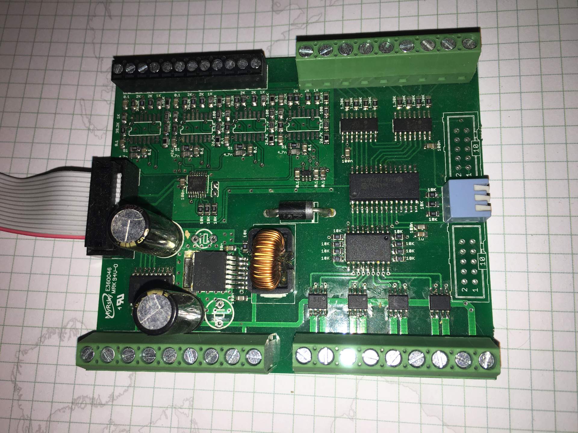
If I'm understanding your request correctly, you're looking for something similar to the photos attached.

In post 1035 by ksullivan86, it is stated that there are not enough gpio pins. I have the same situation, where I need 13 or so for sensors
I don't think there's a CBPi limit, but you may run out with the raspberry pi, which would mean you'd be using some kind of GPIO expansion board in conjunction with it, which would probably mean writing your own plugin. Widgetlords may have some stuff that interests you. The plugins are pretty easy to write, but I think even easier is to just use something like node-red, especially as I imagined you'd be doing some pretty specialized things with this setup...Thank you for your reply. I see where my question may have been unclear. I have 4 one wire temp sensors, which I realize can be used off one pin because of each sensor having a unique serial number. My question is whether the pi has enough pins along with the software to control 13 or 14 devices, with includes gas solenoid valves. I am also not sure if there is a plug-in for gas solonoid valve control. I only see a servo for the gas tank valve. I think these were the questions in the earlier post. Thanks!
You can use http or mqtt actuators, so no pin limit.Thank you for your reply. I see where my question may have been unclear. I have 4 one wire temp sensors, which I realize can be used off one pin because of each sensor having a unique serial number. My question is whether the pi has enough pins along with the software to control 13 or 14 devices, with includes gas solenoid valves. I am also not sure if there is a plug-in for gas solonoid valve control. I only see a servo for the gas tank valve. I think these were the questions in the earlier post. Thanks!
Sonoff Basic reflashed with Tasmota works like a charm.Thanks, all. I had a suspicion that there aren't enough pins unlike the mega. I am slightly familiar with MQTT. I'll look into your suggestions. Thanks!
And yes, flashing a Sonoff is not mutch diferent as flashing a STC1000+
If I can add another question to this question... How would you connect reflashed sonoffs to a RPI or an expansion board like a tarragady that has only 8 inputs/outputs to get the total you need?
Yes, the broker ( mosquitto ) runs on the same Pi as CBPiThanks so much for that. Yes, I would then need the MQTT broker and sonoff solution. The code looks easy enough. The pi would be running craftbrewpi and sending commands through the MQTT broker?
The NOOBS installer comes prebuilt with all the required repos for most applications, whereas the Lite version has none and you need to install all of them yourself. If this is your first rodeo, I'd strongly recommend NOOBS as a starting point, as it's less of a steep Linux learning curve for you.Hi Guys,
I need some help please. I hope this is the right place. I have very little IT knowledge and I am trying to install CraftbeerPi on my RaspberryPi 2B. I have donwloaded Raspbian Stretch Lite and flashed it to my SD card. I inserted the SD card into the Pi and fired it up and the Raspbian installation started. After the installation completed I logged in with the default login details and typed: "git clone https://github.com/Manuel83/craftbeerpi3" and got this error "bash: git: command not found".
I looked around on the internet and it looked like I first had to install Git. I used "sudo apt-get install git". I then tried to run "git clone https://github.com/Manuel83/craftbeerpi3" again and was asked for login in details for my Github account. I have tried to login but it does not seem to be working. On all the videos I watched about installing CraftbeerPi the guy typed in "pwd" and then directly afterwards typed "git clone https://github.com/Manuel83/craftbeerpi3" and it seemed to be working. Am I doing something wrong should I rather install Raspbian through the noobs installer?
Any help will be greatly appreciated.
Did you have the Mod_PWM logic configured for both the kettle and the heating element? I made the mistake of having just one of them set to that logic type and had issues because of it.Did a brew using CBP 3 a few weeks ago which went horrible. The PWM module kept crashing CBP ultimately causing the RPi to crap out altogether, forcing me to do an on-the-fly reinstall of Raspbian and CBP which added about 2 hrs to my brewing day. SWMBO was not pleased. I am kind of done using software based solutions for brewing temp control, will go back to my Auber pid.
Yep, all worked well for a while and then kept crashing every 10 mins until after a reboot the RPi wouldn't come up. I tested the microSD card afterwards which was fine. Wasted another hour trying to get CBP 2 up on Stretch which was a drama. Ended up using CBP 3 on simple mode which actually gets you in the ballpark for mashing.Did you have the Mod_PWM logic configured for both the kettle and the heating element? I made the mistake of having just one of them set to that logic type and had issues because of it.

Hi all,
I left abruptly brewing hobby and took me about 5 years to be back.
Well, before leaving, I was working on a system a bit like the craft beer pi, but was using a beagle bone black because of the processing units and their abilities to act a bit like onboard arduinos and being able to share data with other apps in RAM.
To make it short, regular IOs driven by some software where unable to be fast enough and have a precise timing for the needs of the AD converters and the zero crossing SSR PWM.
I made a few circuits for that purpose and pals on a french board where supposed to make the software.
As example, main board has 4 SSR with 4 PT100 inputs, 8 opto coupled inputs and 8 low amp outputs to drive solenoids or lamps.
There are some other boards like 8 relays, inputs, low amp outputs...
All boards mount in cases made to mount on DIN rail.
All modules are made to be chained on a bus.
I never released anything, but I decided to blow the dust on my stuff and I sent a message to Manuel to tell him I'd like to rework the boards for his system.
I'm waiting for a few components to be able to test his software with the hardware I made.
If some are interested in, I'm setting up a github repository where I'll post the schematics and boards when they'll be tested.
They will be all on i2c bus and for now there is:
- 4 opto inputs + 4 low amp outputs
- 4 relays
- 4 PT100
- 2 flow meters + 2 low amp outputs ( goal is to be able to set a volume and let the circuit pilot a valve to fill a vessel or just measure a flow or a volume. )
- 4 SSR zero crossing 0-100% PWM
- a board for interconnection and power supply to the slave boards
Connection between boards are made using regular network cables. I found it easier on another project for work, so I also moved that to those boards.
I just need to verify some components before placing the PCB order but I hope to be able to get something running to test by october.
Yes it's on i2c , I might do some 1 wire as I already did flowmeters on 1 wire for a commercial project.Nice, if everything is hookup on I2C there are not to many wires connecting the RPi.