• Please visit and share your knowledge at our sister communities:
  • If you have not, please join our official Homebrewing Facebook Group!

    Homebrewing Facebook Group

Can someone look over this wiring diagram?

Homebrew Talk

Help Support Homebrew Talk:

This site may earn a commission from merchant affiliate links, including eBay, Amazon, and others.

ccfoo242

Well-Known Member
Joined
Feb 8, 2012
Messages
85
Reaction score
13
Location
Jacksonville
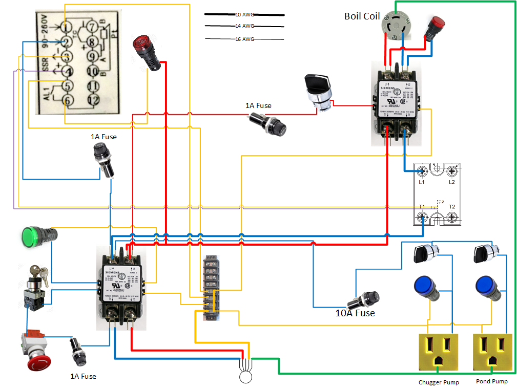
Hi! First a big thanks to everyone on this forum for all of the info I have gleaned this year. I started with one of the PJ diagrams then figured out how to do this in Visio.

I'll be controlling a Blichmann boilcoil for a 15 gallon pot and a pump. The setup will be a copy of Blichmann's EasyBrew system.

fiFbgFh.png


Any comments or criticism is welcome. I plan to build this in 2 weeks.

:mug:
 
Your ssr isn't doing anything for you. L1 and L2 are the switchable load terminals so one leg of your hot going to the element needs to pass through there.

T1 and T2 are the trigger connects from your PID

There are a ton of already done wiring diagrams on here. Proven working ones
 
Your ssr isn't doing anything for you. L1 and L2 are the switchable load terminals so one leg of your hot going to the element needs to pass through there.

T1 and T2 are the trigger connects from your PID

There are a ton of already done wiring diagrams on here. Proven working ones

It wasn't clear to me because the one I have is the Teledyne dual SSR. There's the large terminals with T1 and L1 then small pins numbered 1+- and 2+-.

I thought the trigger voltage from the PID went to the small pins and the high voltage passed through from T1 to L1.

Edit: Here's a pic of the SSR I have:
70105571.jpg

With that SSR, you have it wired properly.

I'd move the switch that controls power to the PID, and have it switch the contactor between the SSR and elements. Might as well have the PID come on with the main power. Having a switch which will reliably disconnect the element power independent of the main system power is a good idea.

Brew on :mug:

Good idea. I'll do that.
 
Looks good, except you don't need 10AWG going to the indicator lights.

Brew on :mug:
 
Back
Top