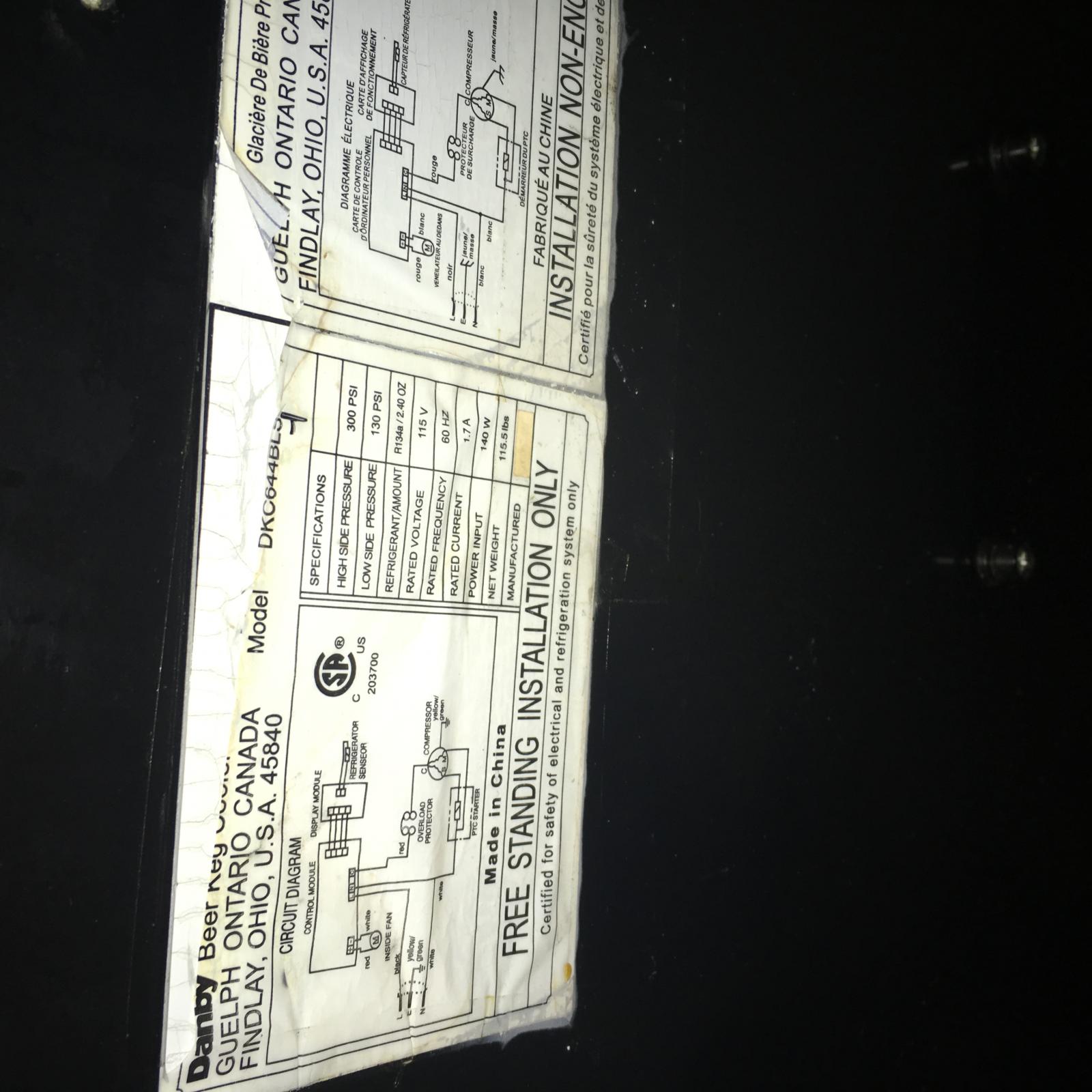
and

Two ways to do this, one easier than the other.
o You wire up your A419 with its own line cord going into it and an outlet going out, plug the fridge line cord into the switched outlet, then remove the Red wire from the controller that goes to the compressor via the overload protector and connect that wire directly to the Black wire feeding the same controller.
With that done you'll control the whole fridge from the A419 via the line cord though it means the display will be pretty much useless.
o Incrementally harder, wire up the A419 input the same way, but remove the same Red wire from the fridge controller, and connect that directly to the A419 relay. That leaves the fridge display functional. You could use a line cord with the Red as Line and grab Neutral and Safety Ground connections for it from the existing wiring.
- In any case, you'll need to connect a 120VAC Line wire to the TB1 "120" contact as shown (this supplies power to the control logic) then daisy-chain the same wire to the "C" contact on TB2 (this supplies power to the output relay Common contact) shown as "RED 1" in the graphic.
- Connect the 120VAC Neutral supply to TB1 AC COM contact.
- Disconnect the red wire from the Control Module that goes to the Overload Protector and Compressor.
- Connect that red wire to the A419 TB2 NO contact ("normally open") shown as "RED 2" in the graphic.
- Wire the sensor to TB3 as shown and run it inside the fridge.
- Make sure the A419 jumpers are set for "Cooling/Cut-out:

- Program the A419 and you should be off and running.
Cheers!


![Craft A Brew - Safale S-04 Dry Yeast - Fermentis - English Ale Dry Yeast - For English and American Ales and Hard Apple Ciders - Ingredients for Home Brewing - Beer Making Supplies - [1 Pack]](https://m.media-amazon.com/images/I/41fVGNh6JfL._SL500_.jpg)


