• Please visit and share your knowledge at our sister communities:
  • If you have not, please join our official Homebrewing Facebook Group!

    Homebrewing Facebook Group

Brand New Controller Failure (Popping Noises)

Homebrew Talk

Help Support Homebrew Talk:

This site may earn a commission from merchant affiliate links, including eBay, Amazon, and others.

CodeSection

Well-Known Member
Joined
Feb 4, 2018
Messages
1,655
Reaction score
819
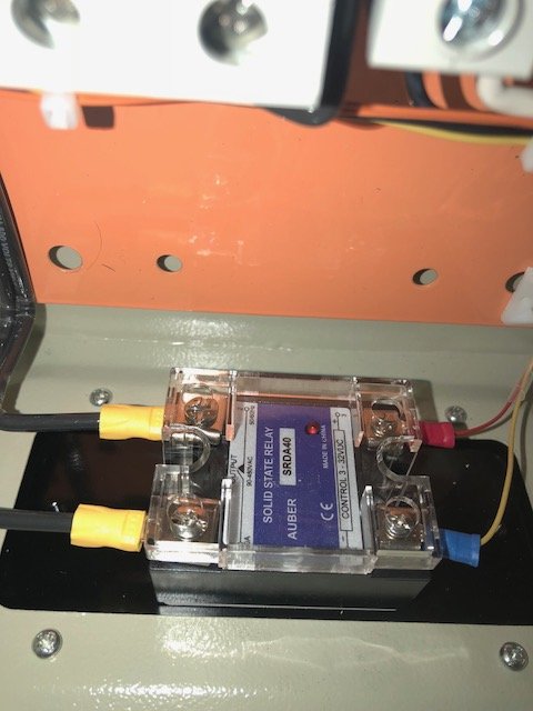
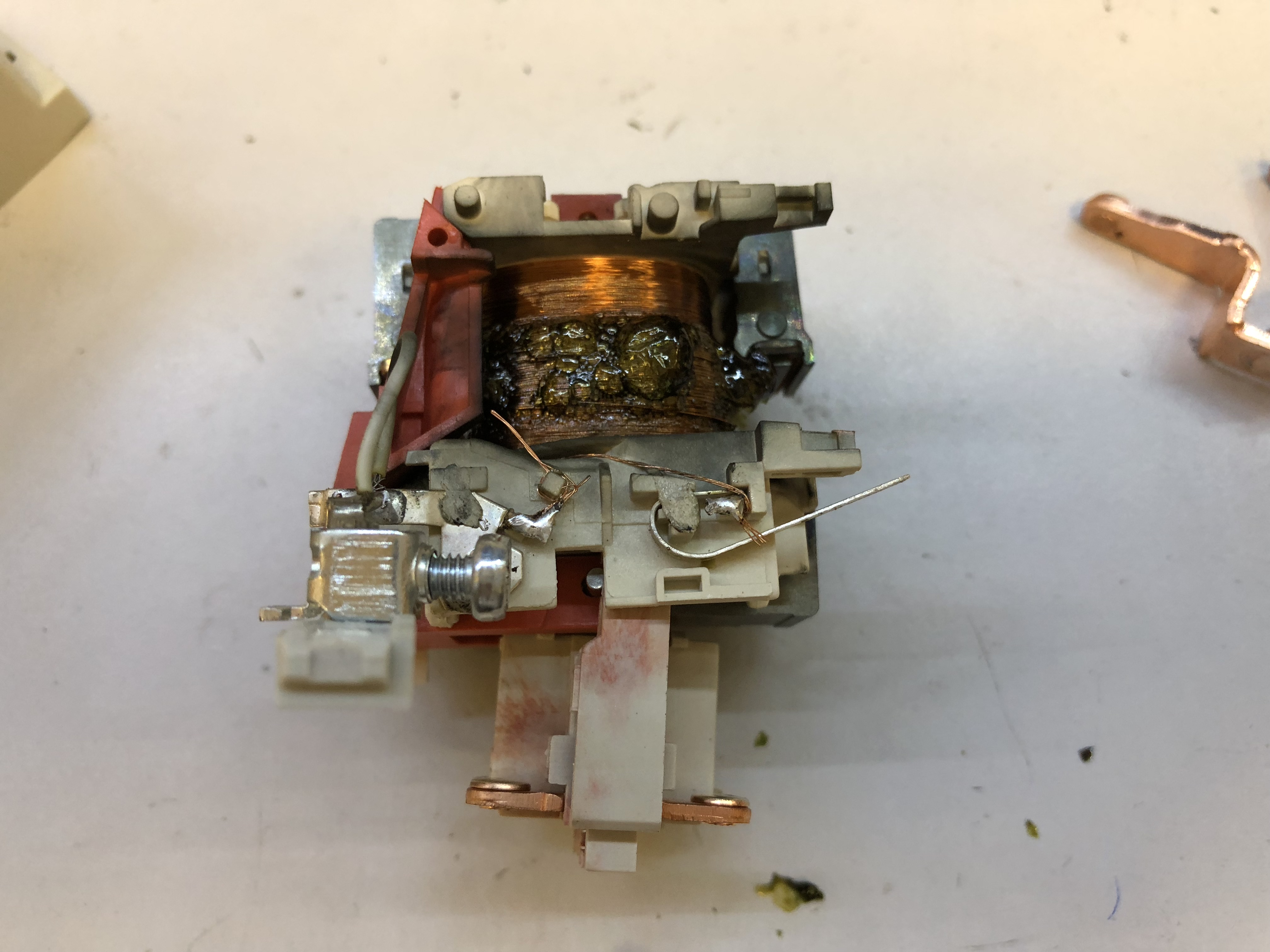
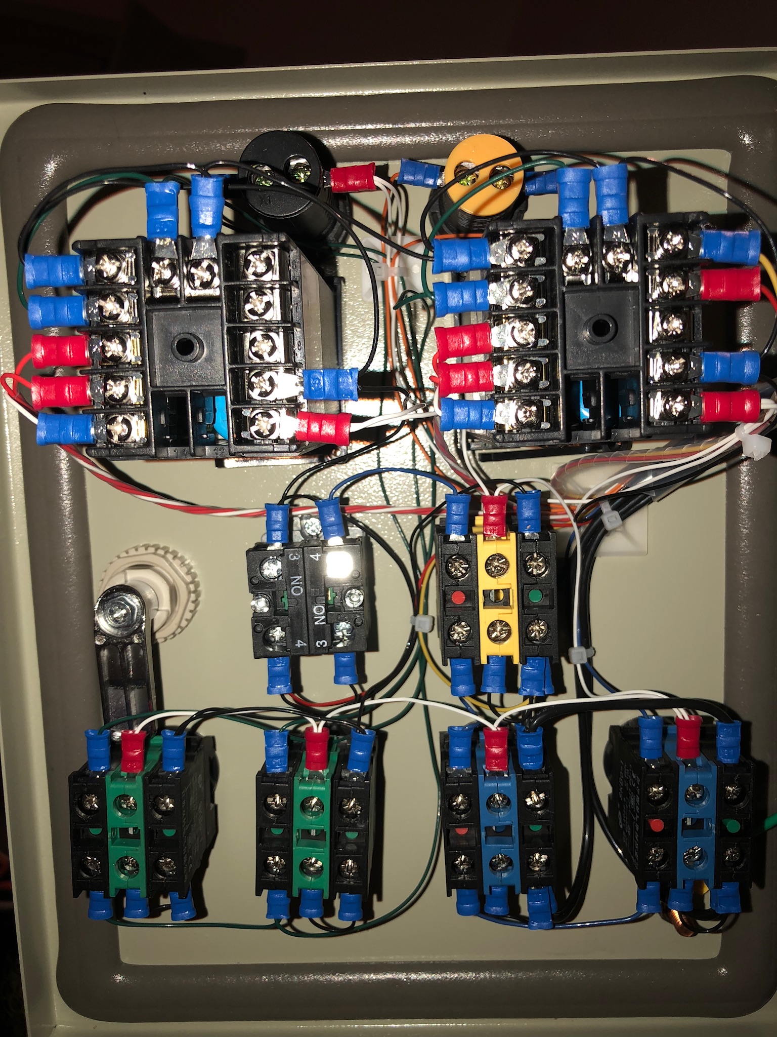
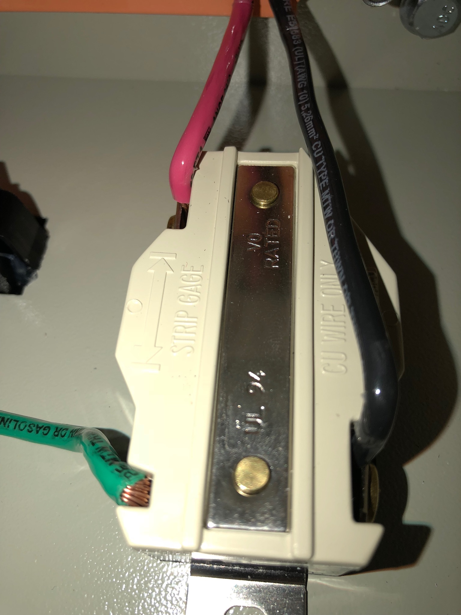
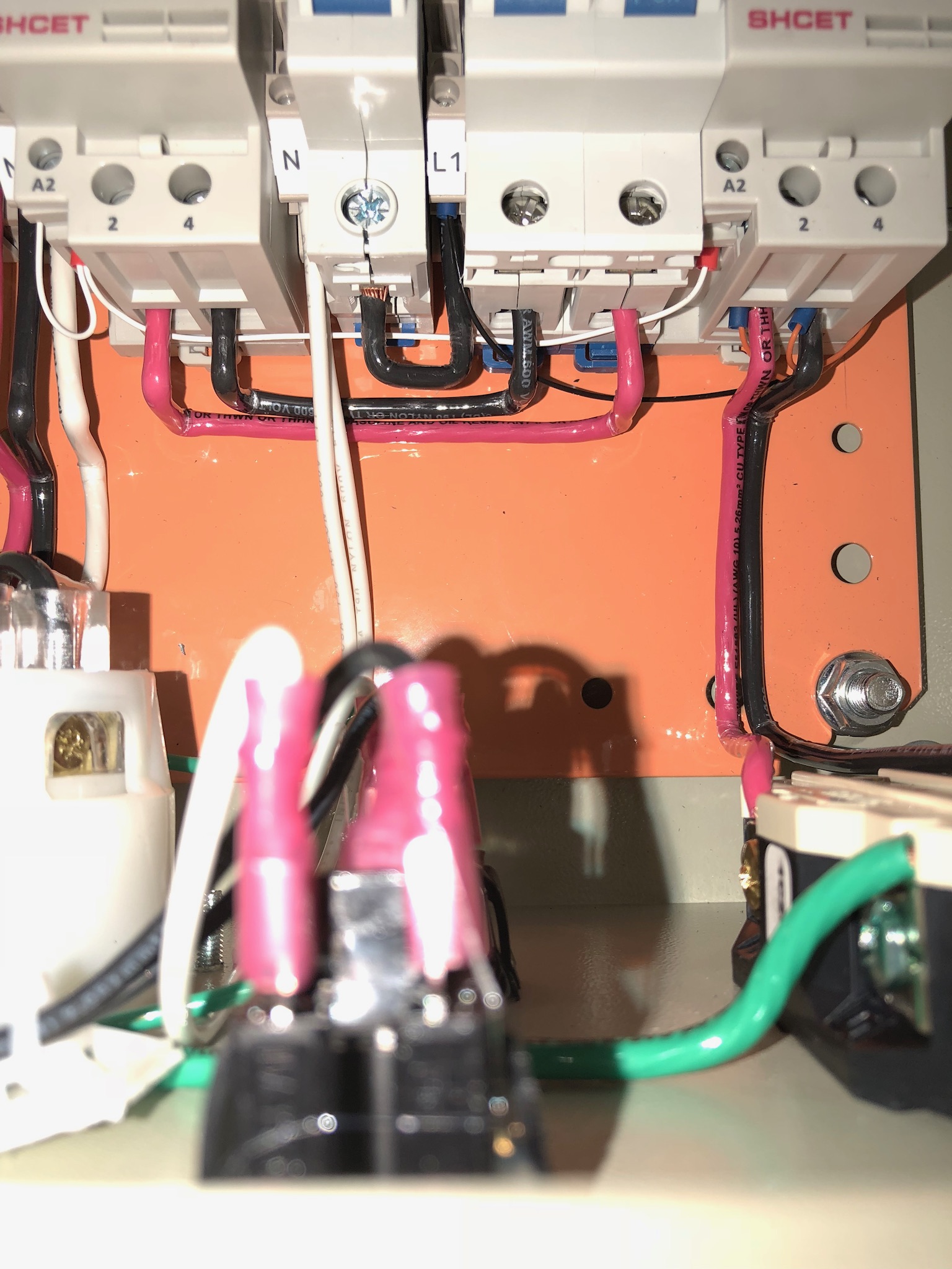
Yesterday, after everything was crushed, hop additions measured, water profile additions added, and 12 minutes into heating my water, my brand new controller made a "pop" noise and the heating element light turned off. When I opened the panel, there was smoke and a smell of wires or plastic burning. The internal circuit breakers did not trip. My electrical 30A breaker did not trip either. I could not see any burning marks on any wires or anything.

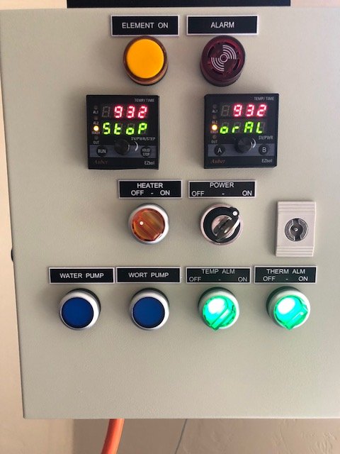
I turned off all breakers and then turned them back on to see if that would reset everything. It did not work. The control panel would still light up with everything turning on except the heating element.

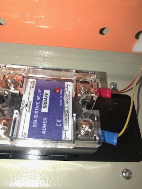
Since this was the first time using the controller, I wanted to test to see if anything else had problems. I decided to see if my pumps would work. I opened the valves and turned on my boil pump and had it recirculating water back into the boil kettle. After a minute, I heard another "pop" and noticed all the lights turned off on the controller. Opened the controller, saw the same smoke as before and smelled the same smell as before. This time the breaker in the controller was tripped. Nothing I tried would turn it back on.

So, yesterday was a disaster for my first all grain brew. I plan on contacting the manufacturer of the controller unit on Monday regarding returning the unit to them.

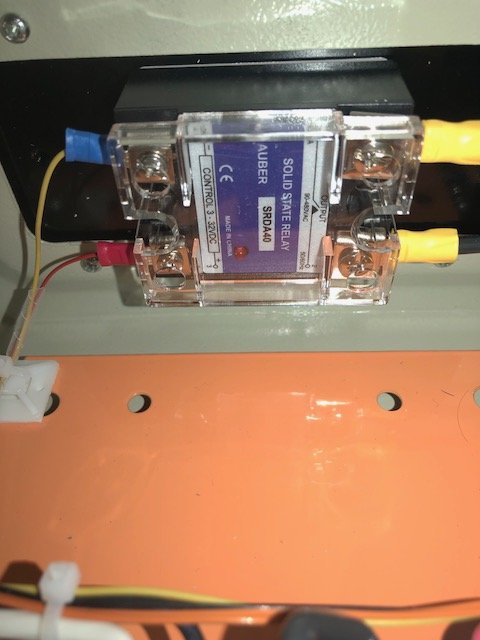
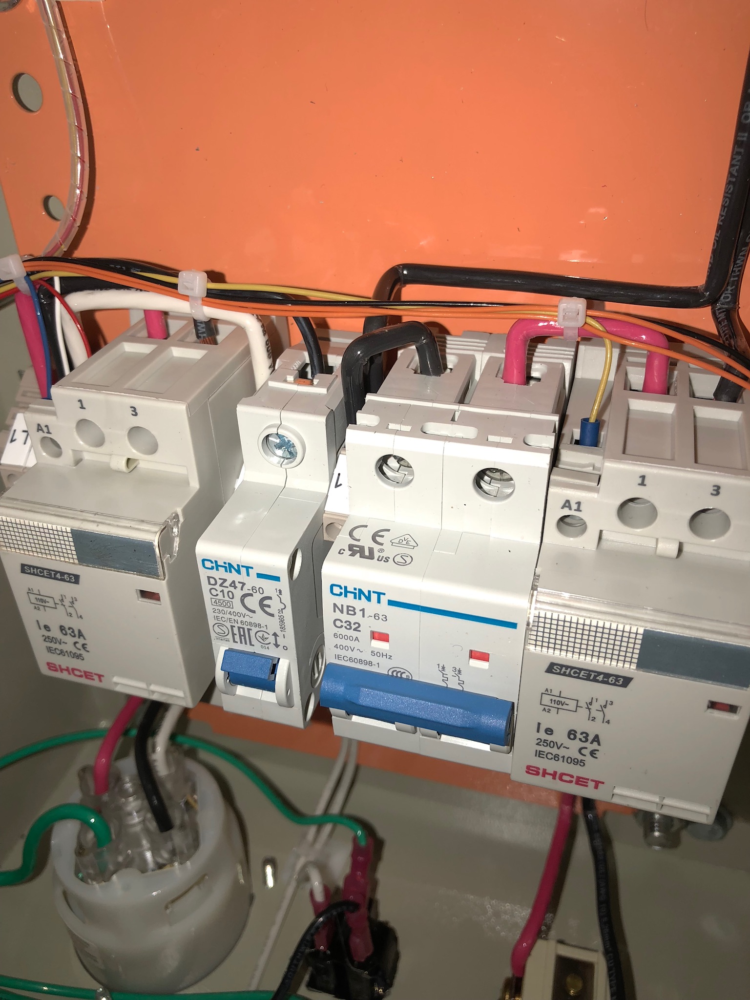
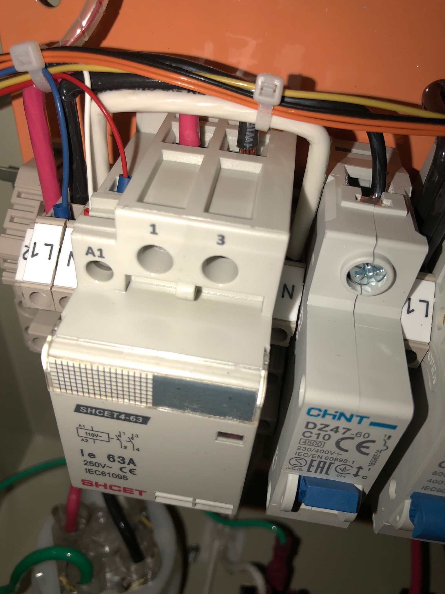
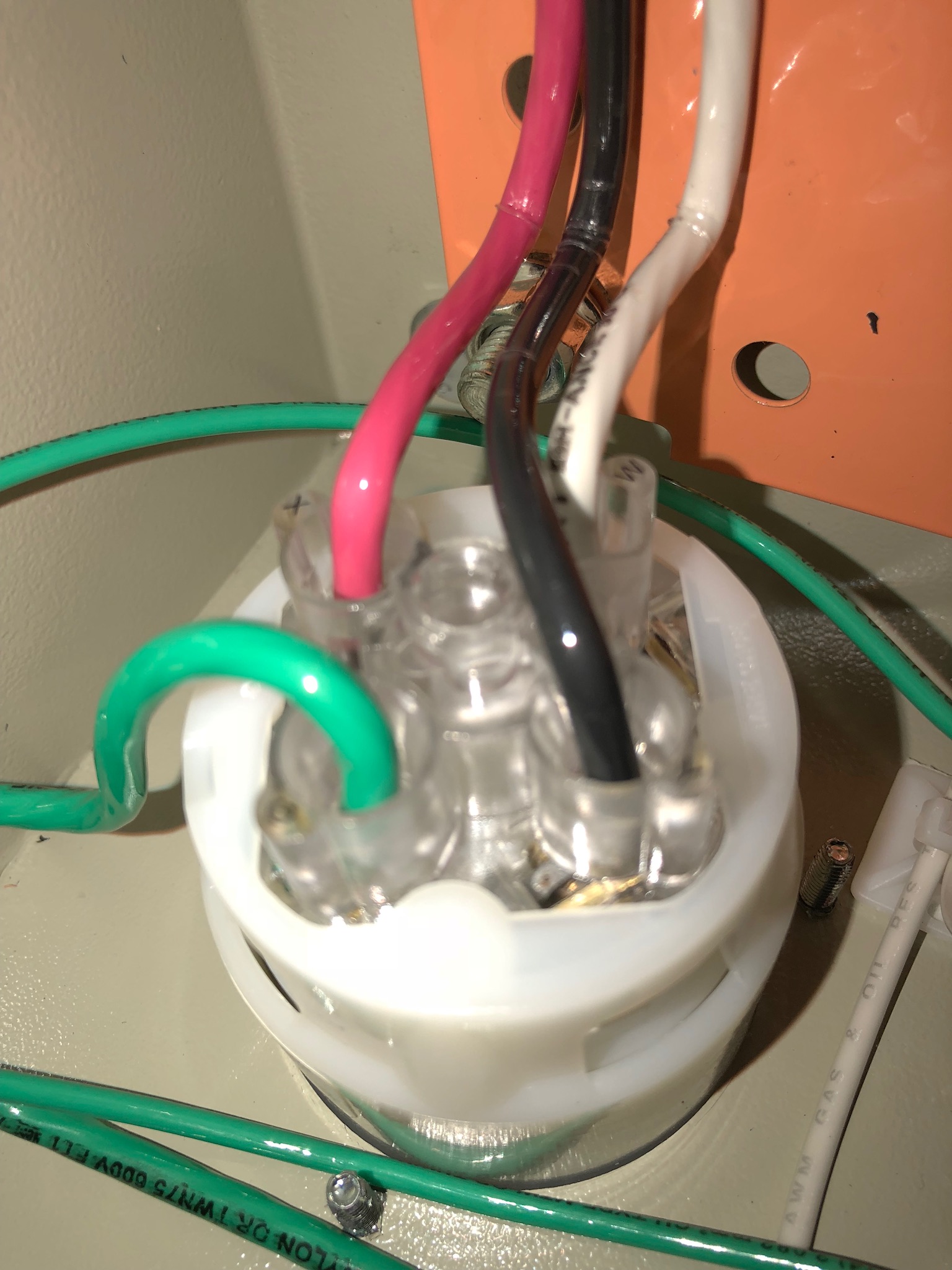
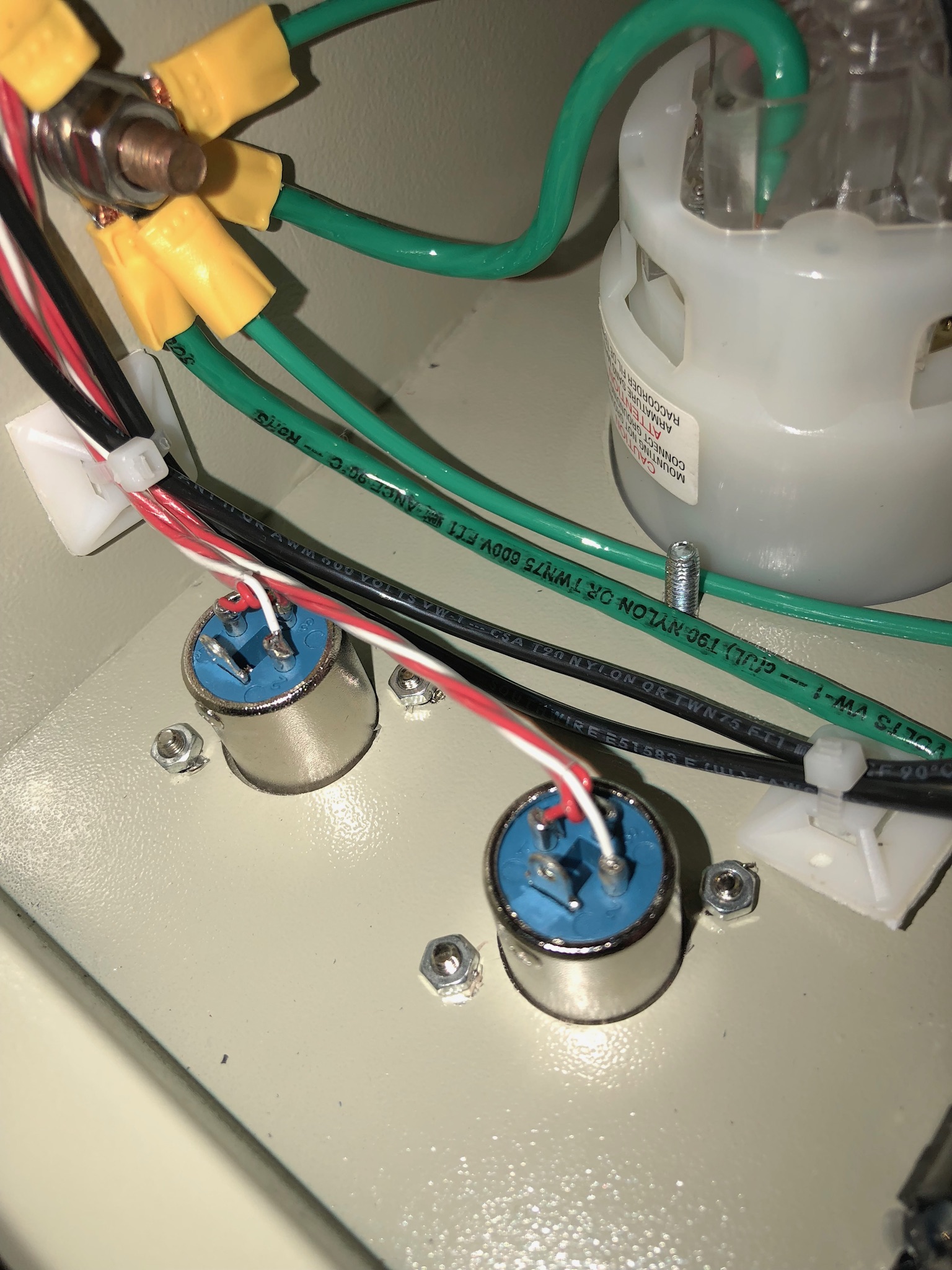
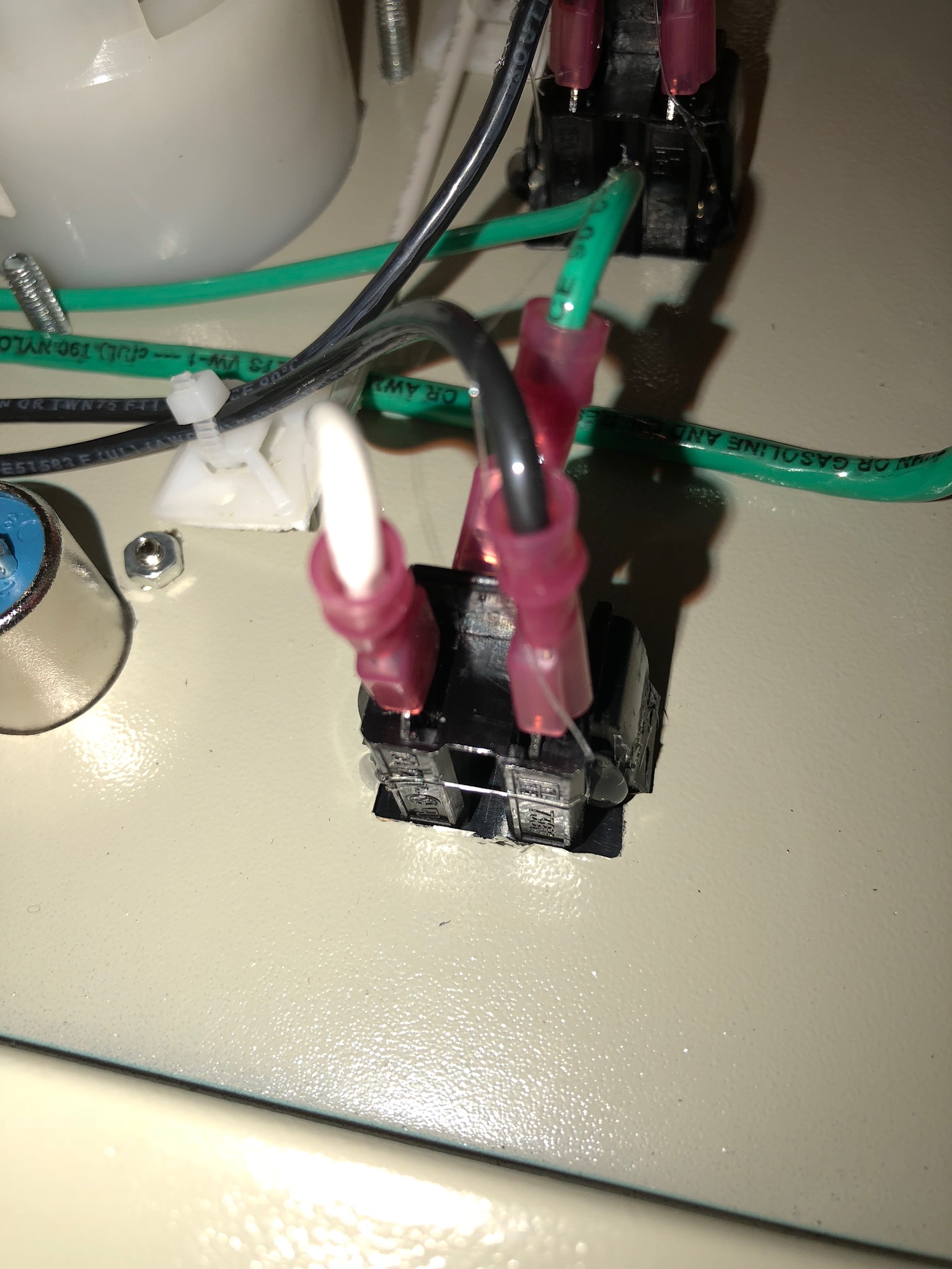
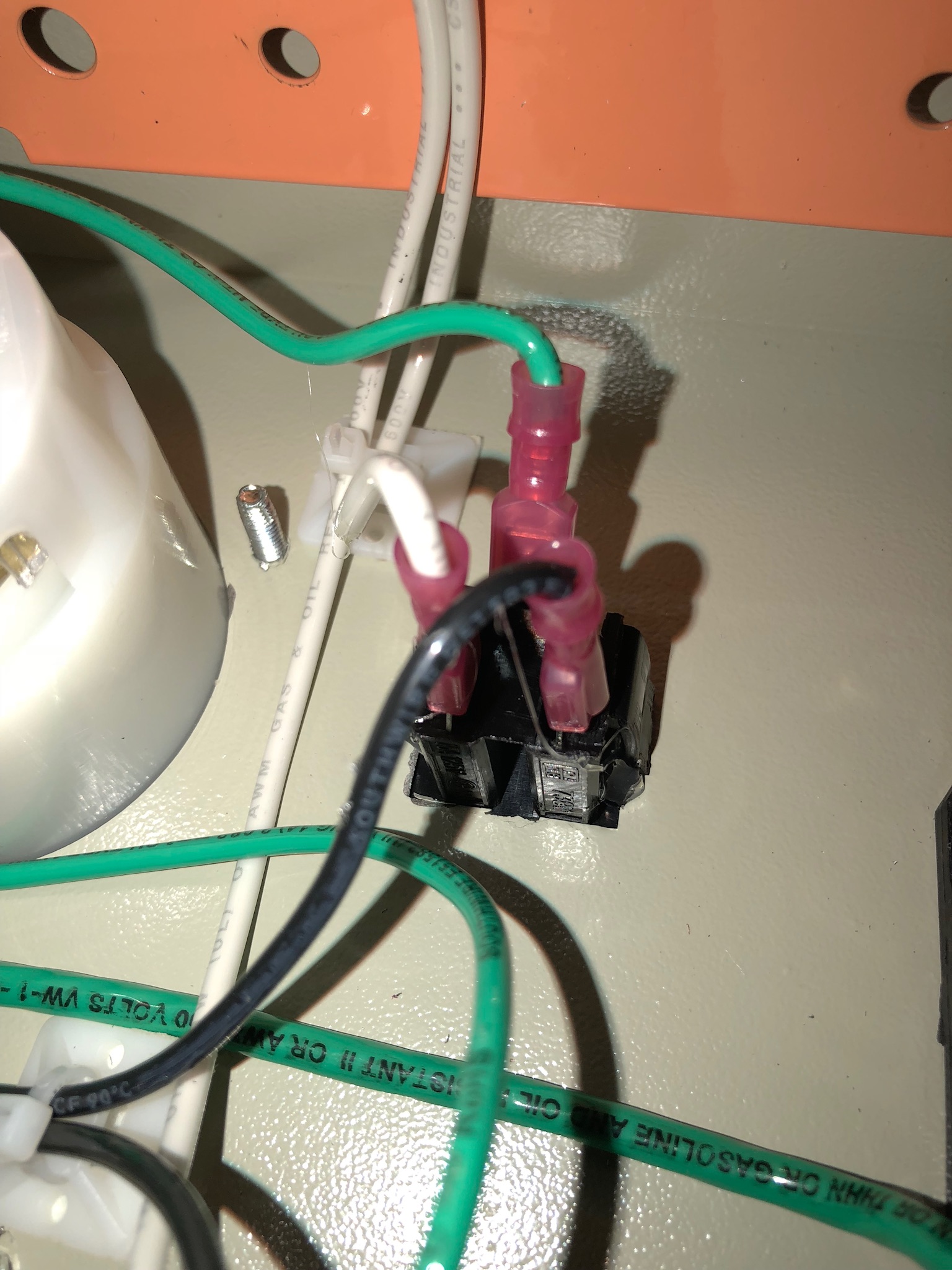
Do you have any ideas why this happened? Could it be bad parts, incorrect wiring or too small wires being used?

To say I was disappointed is an understatement.
 
Sounds like bad parts, or incorrect wiring. Wires that at too small don't tend to "pop" when they burn out. Can you take a bunch of pics of the inside from multiple angles, including close ups? Might be able to see something.

Brew on :mug:
 

Attachments

  • image.jpeg
    image.jpeg
    661.8 KB
  • image.jpeg
    image.jpeg
    697.6 KB
  • image.jpeg
    image.jpeg
    921.5 KB
  • image.jpeg
    image.jpeg
    539.4 KB
  • image.jpeg
    image.jpeg
    498.8 KB
  • image.jpeg
    image.jpeg
    446 KB
  • image.jpeg
    image.jpeg
    415.9 KB
  • image.jpeg
    image.jpeg
    612 KB
  • image.jpeg
    image.jpeg
    518.4 KB
  • image.jpeg
    image.jpeg
    511.7 KB
Last edited:

Attachments

  • image.jpeg
    image.jpeg
    550.4 KB
  • image.jpeg
    image.jpeg
    891.1 KB
  • image.jpeg
    image.jpeg
    927.4 KB
  • image.jpeg
    image.jpeg
    585.2 KB
Looks like a very professional wiring job. Nothing obviously fried in there, but I don't see any pics of the SSR(s) and associated wires.

Brew on :mug:
 
@doug293cz The last post above shows the back of the two EZBoil units. The DSPR310D is on the right when looking at the pic and controls the BK. On the left is a DSPR300 for the MT (there is no heating element on this EZBoil - used for temp probe).
 
image.jpeg
@Sparkncode This is all new to me and so is the terminology. That is why I bought one directly from the manufacturer.

With that said, are these SCRs below the top two EZBoil units?
 
Ok on the brought it. Sucks to have a failure on a purchased solution.
Pity they dont give you a circuit diagram because there is nothing proprietary in this.

Oops i ment ssr but scrs or triacs can be used but nothing there looks like it has wireing capable of the high currents. The twin 63A contactors on the back panel look to be doing the main switch path but without some fast electronic switches the control rate would be fairly slow not the 1s rate many panels cycle at.

There might be some fat wires going from the 63A contactors on the back panel to an electronic component then to the element output if there is an SSR etc in the circuit.
Usually the main high power electronics let smoke out with a pop but if it wasn't too loud it could have been a bad capacitor inside a PID module etc had an early life failure. Did the pids light up normally after the pop?
 
Any reason the manufacturer of the device is being kept out of the discussion?
Since it was the first use of the equipment, the manufacturer should be the one dealing with any problems.
The forum members would probably be interested in who made the product, how they respond to any inquiries and what they are going to do about it.
 
I agree with madscientist 451. If I had a brand new panel go south on the first try, I would disconnect it, box it up, call the manufacturer and send it back to them. I would not even mess with it. Have you called them yet?
 
@BrunDog Thanks for the directions. Here are pics of the SSR.

@Sparkncode Yes, The EZBoil units did light up after the first "pop" but not after the second "pop". The "pop" was loud and as you can see in the videos, produced smoke.

@madscientist451, @cubalz I am now working with the manufacturer. I would prefer not to mention their name at this point. They have responded and they were hoping I had a multimeter to test some items. Unfortunately, I do not have one.
 

Attachments

  • IMG_0895.jpg
    IMG_0895.jpg
    49.3 KB
  • IMG_0894.jpg
    IMG_0894.jpg
    53.3 KB
  • IMG_0896.jpg
    IMG_0896.jpg
    46.9 KB
I have a pretty good idea of who the manufacturer is, and I have used them in the past. I am sure it was just a parts problem, every interaction I have had was super positive .

Best of luck
 
@madscientist451, @cubalz I am now working with the manufacturer. I would prefer not to mention their name at this point. They have responded and they were hoping I had a multimeter to test some items. Unfortunately, I do not have one.

You really should have a multimeter if you’re doing electric brewing. A good enough one can be had for about $20-30.
 
This may sound odd but if you smell the components youll probably find the ssr popped and smells burnt .. failure is not common with these MGR made ssrs.. im sure Auberins will take care of it for you.

You can see if the light on the ssr still turns on as that can be one indication.. Even if it does though its likely the failure you had.
Based on the PN on the SSR, it looks like OP has an older generation Auber SSR from someone other than Mager.

Brew on :mug:
 
I'm happy to report the manufacturer has been very responsive. They want me to mail them the controller back which hopefully will be tomorrow. They appear to be puzzled by this as well.

I should be able to borrow a multimeter tomorrow morning. I know the manufacturer wants the heating element tested even though there are no marks on it. So, either I can test it myself or send it back with the controller for them to test.

@schematix You are probably right. Is there a particular brand or model you or anyone else recommend? It doesn't need to be rated for 30Amps, correct? Home Depot has a large selection, plus their return policy is pretty good.

@augiedoggy I'll check it to see if it lights up once I get home. Thanks for the suggestion.

When I was taking more pictures this morning, I noticed the boil pump switch was still depressed. I pushed it so it would go into the off position and then I attached the 240v line to the controller. When I turned on the controller, both the DSPR310D and the DSPR300 lit up. When I turned on the alarms, both lit up as well.

However, when I turned on the element or pushed one of the pump's buttons, the controller turned off. Perhaps, it was due to nothing being attached to them? Here are the pics of that....
IMG_0899.jpg
 

Attachments

  • IMG_0900.jpg
    IMG_0900.jpg
    50.6 KB
  • IMG_0901.jpg
    IMG_0901.jpg
    50.8 KB
  • IMG_0902.jpg
    IMG_0902.jpg
    49.9 KB
I'm happy to report the manufacturer has been very responsive. They want me to mail them the controller back which hopefully will be tomorrow. They appear to be puzzled by this as well.

That's great news. Hopefully it will get fixed and soon and you'll be back brewing.
But I have to call things as I see it. Disclaimer: I already know I'm an opinionated A-hole.
The OP comes on this site asking for help and all gets all kinds of responses from people trying to help deal with the issue.
Yet the OP doesn't want to provide information about who made the product.
Basically he (or she) sucks up all the help they can get but wants to keep secrets for some unknown reason.
That's not the way this is supposed to work; a free flow of ideas, opinions, knowledge, and experiences goes around and around and everyone benefits.
If the manufacturer fixes a problem, then that's great publicity for them.
If they don't, they deserve whatever bad press they have coming their way.
OK rant over, I'm going to keg up some beer and drink a little bit too.
:mug:
 
@madscientist451 I certainly can understand your perspective. This web site has been a great help to me and I hope to someday return all the kindness I have received. At this point, since the issue has not been resolved, I see no point in disclosing the manufacturer that could cause unnecessary ill-will or drama to them. Once it is resolved, I will gladly report who the manufacturer was, how I was treated and how the issue was resolved.

By starting this post, I was hoping that members like yourself could share some insights into my problem so as I have a better understanding of the controller and components and what could have gone wrong. At the same time, it educates me so that I may be better informed when talking with the manufacturer. It should be obvious by now of my lack of education in dealing with controller terms and parts. @BrunDog was kind enough to educate me on what to look for and where.

@madscientist451 I hope this helps explain my actions. There are no secrets, no agendas. I am just doing what I would hope someone else would do and extend the same courtesy to me someday.
 
@schematix You are probably right. Is there a particular brand or model you or anyone else recommend? It doesn't need to be rated for 30Amps, correct? Home Depot has a large selection, plus their return policy is pretty good.

Amperage isn't important unless you are trying to measure current, which is very impractical in just about any real application. The ones at home depot or lowes will suit you fine. Pretty sure i bought mine there.
 
I have a large nu.ber of meters including higher end flukes and honestly for this, a $6 harbor freight multimeter will work just fine and be plenty accurate enough but that's just my opinion . I have so many free ones that come in the coupon ads I keep them in my vehicles and places like the brewery and my camp trailer.. they actually work well

Btw your symptoms sound like the main power contactor has a bad contact that is failing under load but it's just a guess at this point.
 
@augiedoggy I turned on the power and the red light on the SSR does not light up. I can't tell where the smell is coming from.

Could this explain why both the 240v element and the 110v pump stopped working? Does the SSR influence both of those devices?

On another note, I never thought of Harbor Freight. My mind is wired for Home Depot. Thanks for the reminder.
 
The SSR shouldn't affect the pump, unless the SSR has an internal short that is causing the circuit breaker to trip.

Brew on :mug:
 
@doug293cz Thanks for explaining. As seen in the second video, when the pump stopped, the circuit breaker inside tripped. The pump still works, so I am not sure why the circuit breaker tripped.

I tried sniffing around inside the controller and quite frankly everywhere I sniffed, I smelled the same plastic burning smell. The smoke gave everything a smell.

Well, I've boxed everything up so hopefully Tuesday or Wednesday it will ship out.
 
It sucks to have an early failure but it happens sometimes,
hopefully they get it fixed and back to you real quick or another one so you can brew on.
:mug:
 
if it were me, I would ask them to ship you a new one after you provide proof of shipping back to them. They could say no, but give them the option to tell you no.....

MX1
 
@madscientist451 and others, I need your help. The manufacturer, Auber Instruments received the controller back today. I am just as confused as before. In my previous emails with them and in a phone conversation, they were thinking the problem was caused by the heating element. They wanted the heating element sent back to them as well as the controller. Even after I tested the ohms on the element with three different multimeters. They said their equipment was better than the HomeDepot equipment (they suggested I buy), however since I was skeptical that they were playing the blame game, I did not send them the heating element that I purchased from a vendor on this board.

After receiving their email today, I as well as my electrician are even more skeptical. Their diagnosis doesn't explain why the controller and heating element worked for about 12 minutes. Surely, the gfci in the panel would have pooped if something was miswired in the receptacle or power cord...

Their email.....
==================================
"Your control panel was arrived today.

Once it came, we checked all the wires/connections and they are all solid connected. Later, our senior engineer tested the control panel with 240V power; he found that there was no click sound when it just turned on. This control panel was powered up by an interlock loop with a contactor. There should be a click sound once the contactor was triggered. This indicated that something wrong with the input contactor. Then he also tried to turn the heater switch to the ON position, everything on the control panel turned off and again no click sound was heard. After took off both input and output contactor off, our senior engineer opened the contactor case and saw the coil inside was melt. Please see photos attached. The melted coil indicated the contactor coil had been applied with 240V.

In US, split-phase 240V power supply has 4 conductor: L1 hot line, L2 hot line, Neutral line and Ground Line. To produce a safer product, most of the 240V control panel was designed to use 120V control parts; for example, the contactor coil we used had 120V coil, the LED block on the switch was 120V, the flashing buzzer was 120V. 120V can be produced by using neutral line and L1/L2 line.

If you wired the input connector (L14-30R) properly, you should have L1 to X, L2 to Y, Neutral to W, Ground to G. L1 and L2 can be interchanged (L1 to Y, L2 to X), but the other conductor cannot be reversed.

In this case, our testing result indicated the contactor was bad due to a wrong power input supply; you must had one of the hot line fed to the neutral line on the BB200H control panel and that caused both of the contactors coil melted. Please check both of your power cord connector and also the subpanel wiring; either of that had a wrong hot line fed to the neutral.

After we replaced the two contactors, the control panel worked perfectly. Our warranty service covers labor cost, parts cost, shipping cost for manufacturer fault but does not cover improper usage.

The control panel can be shipped back to you once the payment is completed."

==========================================

My electrician is coming out tomorrow morning to check the receptacle. It appears Auber Instruments is saying it is the subpanel's fault, or the receptacle's fault or the power cord's fault. To me as a consumer, it appears the blame game.

I wrote them an email back saying if there was a problem with the receptacle, power cord or subpanel, I will pay for the repairs, otherwise I expect them to make the repairs for free.

Obviously, I will have confirmation from my electrician tomorrow morning. In the meantime, what are your thoughts? I have attached their pictures.
 

Attachments

  • IMG_1899-1.jpg
    IMG_1899-1.jpg
    1.3 MB
  • IMG_1900-1.jpg
    IMG_1900-1.jpg
    1.1 MB
  • IMG_1901-1.jpg
    IMG_1901-1.jpg
    1.3 MB
@madscientist451 and others, I need your help. The manufacturer, Auber Instruments received the controller back today. I am just as confused as before. In my previous emails with them and in a phone conversation, they were thinking the problem was caused by the heating element. They wanted the heating element sent back to them as well as the controller. Even after I tested the ohms on the element with three different multimeters. They said their equipment was better than the HomeDepot equipment (they suggested I buy), however since I was skeptical that they were playing the blame game, I did not send them the heating element that I purchased from a vendor on this board.

After receiving their email today, I as well as my electrician are even more skeptical. Their diagnosis doesn't explain why the controller and heating element worked for about 12 minutes. Surely, the gfci in the panel would have pooped if something was miswired in the receptacle or power cord...

Their email.....
==================================
"Your control panel was arrived today.

Once it came, we checked all the wires/connections and they are all solid connected. Later, our senior engineer tested the control panel with 240V power; he found that there was no click sound when it just turned on. This control panel was powered up by an interlock loop with a contactor. There should be a click sound once the contactor was triggered. This indicated that something wrong with the input contactor. Then he also tried to turn the heater switch to the ON position, everything on the control panel turned off and again no click sound was heard. After took off both input and output contactor off, our senior engineer opened the contactor case and saw the coil inside was melt. Please see photos attached. The melted coil indicated the contactor coil had been applied with 240V.

In US, split-phase 240V power supply has 4 conductor: L1 hot line, L2 hot line, Neutral line and Ground Line. To produce a safer product, most of the 240V control panel was designed to use 120V control parts; for example, the contactor coil we used had 120V coil, the LED block on the switch was 120V, the flashing buzzer was 120V. 120V can be produced by using neutral line and L1/L2 line.

If you wired the input connector (L14-30R) properly, you should have L1 to X, L2 to Y, Neutral to W, Ground to G. L1 and L2 can be interchanged (L1 to Y, L2 to X), but the other conductor cannot be reversed.

In this case, our testing result indicated the contactor was bad due to a wrong power input supply; you must had one of the hot line fed to the neutral line on the BB200H control panel and that caused both of the contactors coil melted. Please check both of your power cord connector and also the subpanel wiring; either of that had a wrong hot line fed to the neutral.

After we replaced the two contactors, the control panel worked perfectly. Our warranty service covers labor cost, parts cost, shipping cost for manufacturer fault but does not cover improper usage.

The control panel can be shipped back to you once the payment is completed."

==========================================

My electrician is coming out tomorrow morning to check the receptacle. It appears Auber Instruments is saying it is the subpanel's fault, or the receptacle's fault or the power cord's fault. To me as a consumer, it appears the blame game.

I wrote them an email back saying if there was a problem with the receptacle, power cord or subpanel, I will pay for the repairs, otherwise I expect them to make the repairs for free.

Obviously, I will have confirmation from my electrician tomorrow morning. In the meantime, what are your thoughts? I have attached their pictures.
Sorry to say it, but there is a good chance that Auber Instruments is correct. I'm strictly an amateur electrician, but the scenario they describe would produce those results. When I built my panel, I stuck with 240v throughout to make sure I didn't mess it up. I guess we'll know for sure tomorrow. Sorry for your loss. [emoji53]
 
@ancientmariner52 I appreciate your feedback. I'm not sure what you mean "240v throughout". Isn't their build a standard build that uses 240v? If it is 240v, other than for the pumps, why are 120v parts used? I really do not understand.
 
Use your meter and measure the receptacle. L1 and L2 (aka X and Y) should read 240VAC across them. From either to neutral (W) should read 120VAC. From W to ground: near zero. From X or Y to GND: 120VAC. Be careful doing this test... accidentally crossing the probes during this will not necessarily trip a breaker!

Do this test as close to the controller as possible given your current wiring. Keep us in the loop!
 
Last edited:
@ancientmariner52 I appreciate your feedback. I'm not sure what you mean "240v throughout". Isn't their build a standard build that uses 240v? If it is 240v, other than for the pumps, why are 120v parts used? I really do not understand.

It does not have 240 VAC throughout. These panels expect both 240VAC and 120VAC available, assuming they have 4 conductor inputs. House wiring is split-phase - you can google it for more detailed explanation.
 
@ancientmariner52 I appreciate your feedback. I'm not sure what you mean "240v throughout". Isn't their build a standard build that uses 240v? If it is 240v, other than for the pumps, why are 120v parts used? I really do not understand.
In some designs, control power, for fans, indicator lights, meters, fans, and in your case, contactors, use 120v power. I suppose it's cheaper, perhaps safer, but I used all 240v components for simplicity. Worst case, if I mix up wires I send 120v to a 240v component, and no harm done. I hope this helps, I'm really not qualified to mess with this stuff!
 
Use your meter and measure the receptacle. L1 and L2 (aka X and Y) should read 240VAC across them. From either to neutral (W) should read 120VAC. From W to ground: near zero. From X or Y to GND: 240VAC. Be careful doing this test... accidentally crossing the probes during this will not necessarily trip a breaker!

Do this test as close to the controller as possible given your current wiring. Keep us in the loop!
X or Y to GND should read 120V, just like X or Y to Neutral.

Brew on :mug:
 
My experience with Auber is that they are extremely crooked. I 100% regret buying a single component from them. They fscked me and they'll fsck anyone else too. Stay away from those crooked motherfsckign bastards.

They very well could be right here, but to this day my experience with them still makes my blood boil. Vile, crooked, thieves IMHO.
 
@doug293cz and @BrunDog when I got back into town tonight I took the following pictures. If you or anyone else can comment what may or may not be a problem, I would appreciate it. My electrician is coming out early in the morning. If there is a problem, I want it fixed. If he caused the issue, I will gladly pay Auber Instrments for the controller repair and have the electrician reimburse me.

Here are pics of the receptacle and meter readings on different positions....
 

Attachments

  • image.jpeg
    image.jpeg
    741 KB
  • image.jpeg
    image.jpeg
    926.8 KB
  • image.jpeg
    image.jpeg
    624.3 KB
  • image.jpeg
    image.jpeg
    754.1 KB
  • image.jpeg
    image.jpeg
    899.5 KB
  • image.jpeg
    image.jpeg
    865.9 KB
  • image.jpeg
    image.jpeg
    600.4 KB
Here are pics of the power cord and its meter readings...
 

Attachments

  • image.jpeg
    image.jpeg
    779.8 KB
  • image.jpeg
    image.jpeg
    618.3 KB
  • image.jpeg
    image.jpeg
    652.1 KB
  • image.jpeg
    image.jpeg
    604.6 KB
  • image.jpeg
    image.jpeg
    690.3 KB
  • image.jpeg
    image.jpeg
    661.7 KB
  • image.jpeg
    image.jpeg
    629.9 KB
Here are pics of the power cord and its meter readings...
Readings on the power cord are incorrect. The 240V reading should be between the two slots on either side of the "L" shape slot. The L slot is ground. The slot directly opposite is neutral. Going back to your post on the wall socket, it looks like the socket may be the place where the miswiring occurred. It's hard to tell from your pics which reading goes with which slot pair.

Brew on :mug:
 
Back
Top