• Please visit and share your knowledge at our sister communities:
  • If you have not, please join our official Homebrewing Facebook Group!

    Homebrewing Facebook Group

Blown Breaker Troubleshooting - 50a BCS 2 Element

Homebrew Talk

Help Support Homebrew Talk:

This site may earn a commission from merchant affiliate links, including eBay, Amazon, and others.

BrewsByTones

Member
Joined
Feb 6, 2016
Messages
15
Reaction score
0
Looking for some help troubleshooting my build.

I have sourced the parts for this build and am having an issue with one of the 32a breakers and 25a contactors.

http://www.ebrewsupply.com/bcs-50a-2-elements-kit/

One of them is just fine, the heating elements fire and heat quickly and I've actually plugged both heating elements into the inlet that works and both are good, so I can pretty much eliminate anything 'north' of the heating element plugs.

Each time I turn the switch to the problematic heating element, the 32a breaker in the box sparks and flips and the 25a contactor actually goes bad - red indicator in the window.

The first time I did it, I already had the non-problematic heating element plugged in and on and when I turned on the second element not only did the 32a breaker in the box spark and flip + the 25a contactor went but the 50a breaker on my home breaker box tripped.

I have even turned the problematic element switch on with the bad contactor still connected and the 32a breaker in the box still sparks and flips. Not sure if that would happen because the contactor is bad or if that may indicate the 32a breaker has a bad connection or something to that extent.

Anyway, appreciate any feedback, trying to get my electrician friend back out to give it another look but before we tested the system with the peripherals plugged in he reviewed it and thought everything looked good and matched the schema, for what it's worth.

Cheers,
Tony
 
I suspect that the terminal blocks were wired wrong and you've got both elements firing (attempting to fire) when you flip the knob. Remove the load wires from both contactors and verify that the selector switch really does flip flop which contactor coil is engaged.
 
Thank you, Bobby_M and BrunDog for the replies and willingness to help.

------------------------

I suspect that the terminal blocks were wired wrong and you've got both elements firing (attempting to fire) when you flip the knob. Remove the load wires from both contactors and verify that the selector switch really does flip flop which contactor coil is engaged.

There is actually no switch between the contactor coils - both are able to be engaged simultaneously per this particular system design. Instead there are individual switches that turn on each contactor coil and nothing to prevent both from being on at the same time. The 50a design is supposed to be able to accommodate that, but it's certainly possible I misunderstood.

------------------------

Without a schematic, it would be tough to troubleshoot. Do you have a VOM (meter)?

Apologies, I should have linked the schematics - here it is:
https://ebrewsupply.s3.amazonaws.com/schematics/50a-2E-BCS-Kit-2014.pdf

(note there are a couple of typos in the schematics - i.e. the first page lists a 50a GFCI but the second page shows a 30a GFCI in the same spot - I have found these typos to be minimal and have accounted for those mistakes in the documentation)

I do have a VOM and have successfully tested the current/connection in general but to be honest this level of power is a little daunting to me so I've not ventured into testing the actual voltage, etc. I would be more comfortable inviting a professional in to do that.

------------------------

I hope this helps and again appreciate any assistance in troubleshooting. Will keep everyone posted if I/my Electrician friend figure out the issue at hand.

Cheers,
Tony
 
Yes, if your system is fed by an appropriate 50A supply, then both elements can be on. I do it with mine (really only during cleaning).

That schematic is solid, so the first thing you need to do is trace every wire and compare it to the schematic. I suggest you print it out and highlight each line when you cross reference it to the wire. It would be great to also mark off the wires, but I know that's not practical.

Then use your VOM, with the power UNPLUGGED and the elements connected, and work backwards from the elements, checking conductivity (using that function or just resistance function if that's what your meter has). Check there is conductivity where it should be and no conductivity where it shouldn't be. The resistance across the element legs should be appropriate for that element (say ~11 ohms for a 5500W), and from leg to ground or leg to neutral should be open.

Once you get to the SSR or contactor, just keep working backwards but know you can't check for the resistance as the SSR will be funny and the contactor is open. But continue to check for incorrect ties to neutral or ground.

You'll find it.

This is awesome, thank you - it did not even cross my mind to check that there is NO conductivity where there shouldn't be. I have largely checked for conductivity where there should be but this increases my confidence in that procedure so I will go back through a bit more thoroughly and heed your advice regarding referencing the schematics.

Thanks again - will keep you posted on progress.

Cheers,
Tony
 
Then use your VOM, with the power UNPLUGGED and the elements connected, and work backwards from the elements, checking conductivity (using that function or just resistance function if that's what your meter has). Check there is conductivity where it should be and no conductivity where it shouldn't be. The resistance across the element legs should be appropriate for that element (say ~11 ohms for a 5500W), and from leg to ground or leg to neutral should be open.

Once you get to the SSR or contactor, just keep working backwards but know you can't check for the resistance as the SSR will be funny and the contactor is open. But continue to check for incorrect ties to neutral or ground.

Taking this advice I believe I have sourced the issue to a bad (and cheap - i.e. cheaply made) SSR. The SSR on the side of the element that is causing the flip appears to always have conductivity despite the fact that it should be closed unless the input tells it to open.

So, easy fix, I'll just replace the SSR. However, any thoughts or words of wisdom as to why that SSR may have gone bad in the first place? Tough to tell the order of events - for all I know it went bad when everything blew the first time and replacing it and the contactor could produce the exact same results. There is plenty of thermal grease on an overkill heatsink and furthermore neither element has ever been run for terribly long (like a minute or so max) so I don't think the system has even reached a temperature that would have caused the SSR to go bad from that perspective.

Aside from that I feel confident I've checked that conductivity exists everywhere it should and does not exist everywhere it should not. I'll have someone else do an independent pass just to make sure I didn't miss anything but appreciate any additional thoughts as I wait on a new SSR to ship.

Cheers,
Tony
 
Update, I swapped the SSR for another one I had laying around and it too went bad (popped the internal breaker) as soon as I flipped it's corresponding element switch on. The contactor did not immediately go bad though.

So then I figured I either have some bad SSRs or something is wrong with my wiring that is causing only the right side to continue to blow. So, I took the SSR from the left side that has consistently worked and plugged it in to the right side, flipped it's corresponding element switch on and once again it too went bad but this time taking the contactor with it - also popped the internal breaker as above.

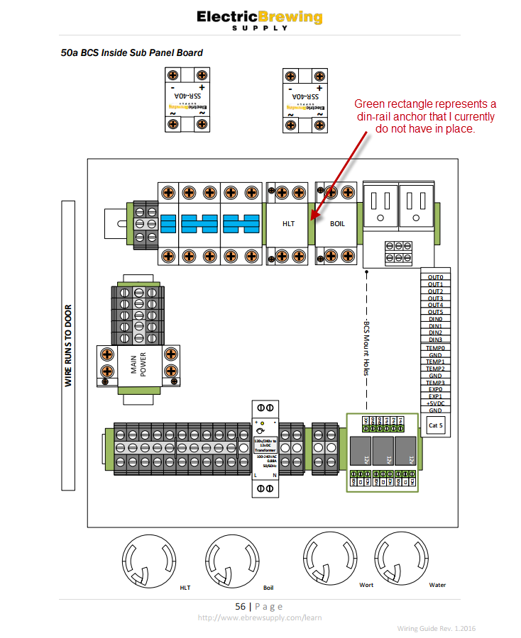
I'm somewhat at a loss but I have on last idea that I'd be interested in feedback on. I failed to separate my two contactors on the din-rail by an anchor as depicted within the full wiring guide found here:
http://guide.ebrew.supply/

Specifically page 56 shows the layout I'm working with. The green rectangle inbetween the two contactors is meant to represent an anchor (defined earlier in the guide). I've attached this page for reference as well.

So, my question is, must those contactors be separated by an anchor? Is it conceivable that by not having them separated by an anchor it is causing the right one to blow? Seems odd to me that it would never cause issues on the left. I did also use a VOM to check that there was no conductivity between the two contactors so based on that I didn't figure it to be a big deal.

Appreciate any feedback on this before I go off and replace more SSRs and Contactors in what feels like futile attempts without some smart advice.

Cheers,
Tony

12-6-2016 12-03-44 AM-edits.png
 
No, the anchor is not the issue.

First off, your contactor should not be getting damaged by an overcurrent situation u less your breaker is oversized or not working properly. I would caution you not to apply power until you ensure the circuitry is correct. Electricity doesn't flow where it can't, and you clearly have a short somewhere. It doesn't sound like a ground fault otherwise that would trip. Your meter should be able to tell you. It also works on one side - why is the other not? Because something is shorted, meaning there is a wire or jumper connecting things that shouldn't be.

If you really want to find it, remember the element should be 10 ohms. Temporarily remove the SSR and jumper across those two poles. Jumper across the contactor poles too. Now measure the conductivity on your input power line. You should get 10 ohms. If you get zero, you know there is a short. You could measure to neutral too but need to remove any power supplies/pumps etc that run on 120V.
 
I know this sounds simple, but do you have both hot1 and hot2 going to the switched side of the SSR? Maybe you have a wire that has the wrong color insulation and it is actually hot1 and hot2? Or maybe it's a hot and a ground? I've blown an SSR that way and it happens the way you describe it.
 
If you really want to find it, remember the element should be 10 ohms. Temporarily remove the SSR and jumper across those two poles. Jumper across the contactor poles too. Now measure the conductivity on your input power line. You should get 10 ohms. If you get zero, you know there is a short.

This isn't my thread, so pardon the potential de-rail.

In hindsight the method above seems bloody obvious, but I would never have thought to do that. Will keep this in mind when I get around to building out my panel. Cheers!

:mug:
 
I'm still not having any luck, unfortunately. Everything checks out. My wiring job is probably a 6/10 on organization so I think I'm just going to un-do it all and go at it again, try to clean things up a bit and inspect the wire casings. I'm wondering if I have a small cut/tear somewhere and perhaps it's causing some arcing.

Even if not, at least it'll be a little cleaner.
 
Back
Top