Automation with Arduino

Homebrew Talk - Beer, Wine, Mead, & Cider Brewing Discussion Forum

Help Support Homebrew Talk - Beer, Wine, Mead, & Cider Brewing Discussion Forum:

This site may earn a commission from merchant affiliate links, including eBay, Amazon, and others.

bheinecke

Well-Known Member
Joined
Jan 21, 2014
Messages
45
Reaction score
20
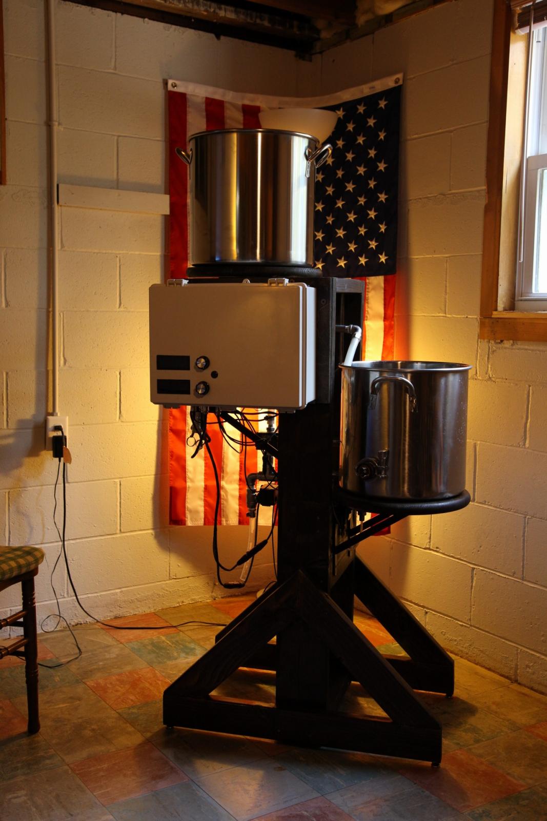
Just a teaser at the moment. This is a 2-vessel brew stand which is more or less automated to the goals below. The controller is an Arduino Mega.

Goal of stand
  • load grain
  • enter recipe
  • return to find a carboy with cooled wort ready for yeast
  • all sensor data & key variables from session logged to SD card for post mortem
  • user interface to monitor progress & provide inputs to system
  • easy cleaning
In other words, allow me to continue brewing with two kids under two


Planned activities for the next 3-ish months
  1. Calibrating the water level sensor this week -- Good enough for initial testing. Will improve later
  2. Connecting to house water supply this weekend (followed by fixing leaks ;)) -- 1x v.slow leak so far
  3. Simulating brew sessions for a couple more weeks (i know there are bugs hiding in there)
  4. Moving to a new-to-me home (no progress for a month)
  5. Hopefully brewing in November

Planned posts in no particular order
  • Overall layout & process flow -- Posts 7,8,9
  • BOM and $$$ -- Post 15
  • Controller & electrical enclosure build -- Post 16
  • The brew stand & associated hardware
  • Sensor calibration & accuracy
  • Open issues and requests for help on things that aren't as good as I would like
  • BREW DAYS!

Until then... 'Merica

USA stand.jpg
 
Just a teaser at the moment. This is a 2-vessel brew stand which is more or less automated to the goals below. The controller is an Arduino Mega.

Goal of stand
  • load grain
  • enter recipe
  • return to find a carboy with cooled wort ready for yeast
  • all sensor data & key variables from session logged to SD card for post mortem
  • user interface to monitor progress & provide inputs to system
  • easy cleaning
In other words, allow me to continue brewing with two kids under two


Planned activities for the next 3-ish months
  1. Calibrating the water level sensor this week
  2. Connecting to house water supply this weekend (followed by fixing leaks ;))
  3. Simulating brew sessions for a couple more weeks (i know there are bugs hiding in there)
  4. Moving to a new-to-me home (no progress for a month)
  5. Hopefully brewing in November

Planned posts in no particular order
  • Overall layout & process flow
  • BOM and $$$
  • Controller & electrical enclosure build
  • Sensor calibration & accuracy
  • Open issues and requests for help on things that aren't as good as I would like
  • BREW DAYS!

Until then... 'Merica

Subscribed.

I am also using a 2 kettle system, mostly automated using a BCS. I used a timer with a flow restrictor to fill the kettle. Have 3 2-way automated valves and 3 3-way automated valves. Also have 2 flow switches and multiple temp probes.

Did my inaugural run a few weeks ago, overshot the initial water. But have since adjusted and ready for round 2, once my ferment chamber is empty.


Couple of questions

What are you using to control the temp for the Mash? Rims, recirculate from BK (What I am doing) or ?
No ventilation? Are you going to be brewing inside?
What software for the Arduino? Kicking around updating to Arduino from BCS at some point.

:mug:
 
I am also using a 2 kettle system, mostly automated using a BCS. I used a timer with a flow restrictor to fill the kettle.

Kick me later but what does "BCS" stand for?

I am using a relatively inexpensive pressure sensor to predict water volume. The proof of concept is shown in posts 25 & 30 from linked thread.

https://www.homebrewtalk.com/showthread.php?t=591727&page=3

Did my inaugural run a few weeks ago, overshot the initial water. But have since adjusted and ready for round 2, once my ferment chamber is empty.

Do you have a thread somewhere to show your system? I am curious.

What are you using to control the temp for the Mash? Rims, recirculate from BK (What I am doing) or ?
RIMS via plate heat exchanger. I'll show this in detail at a later time.

No ventilation? Are you going to be brewing inside?
Will be a garage queen. I haven't started on ventilation yet but I will need it.

What software for the Arduino? Kicking around updating to Arduino from BCS at some point.
I used the Arduino IDE to write my programming. I used a fair number of libraries from the webs in my code.
 
Will you have a HMI Screen for recipe setup and HOA control? I had thought about using a micro controller as the steps could easily be programmed and hardware would be cheaper but couldn't find a good solution for a hmi. Decided on a micrologixs plc, quicker to code (for me anyways) and plenty of hmi options from panel view, c-more or ignition to name a few. Would love to see your code as I'm not well versed in Arduino code, just played around a bit.
 
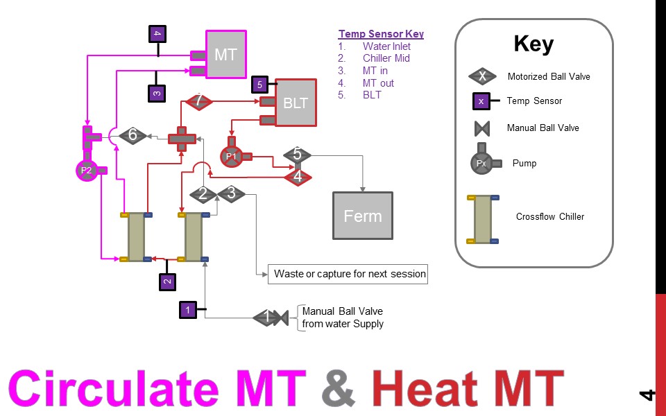
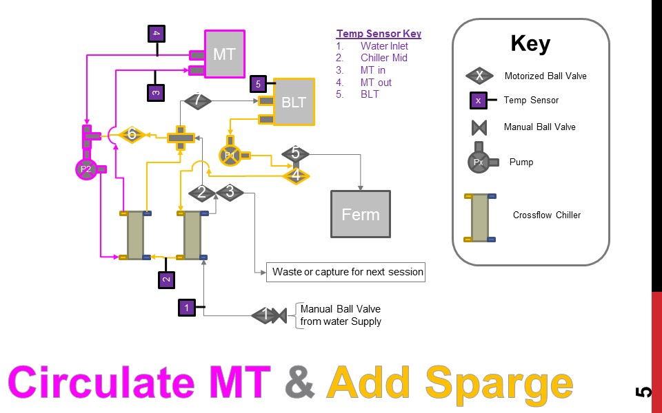
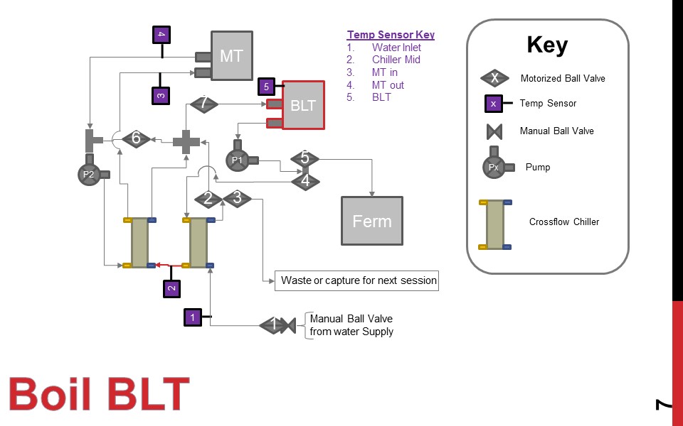
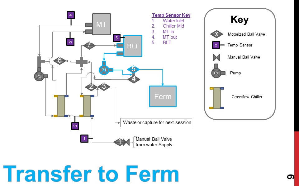
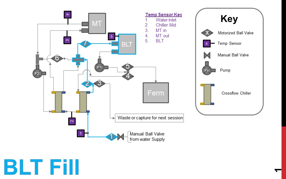
I am not using any sort of standard for these so you'll need to refer to the key to know what is what in the drawings.

Temp sensor locations are labeled. I am monitoring pressure on the bottom of the BLT for liquid volume estimation but it is not shown in the drawings.

Also... BK + HLT = BLT... Its a two vessel system and I like the sound of it sooo....:)

Not sure how best to do this so I am going to lay these out in several posts to make it easier if questions come up later.

View attachment Layout 18 Process Flow.pdf
 
Step 1: Add water to BLT
Minimum of:
- Strike Vol + Sparge Vol + Buffer + Vol to circulate in BLT for MT heating
- BLT Max Vol

Step 2: Circulate BLT while heating to strike temperature
- 5.5kW heating element located in BLT (only one in system)

Step 3: Move strike volume to MT (pump)

Slide1.JPG


Slide2.JPG


Slide3.JPG
 
Step 4: Manage temperature of MT by transfering heat from BLT water to MT via crossflow chiller.

Step 5: Move 'Sparge' water to MT. I am probably abusing the term 'Sparge' in this case but you get the idea. -->Move more hot water to MT to thin out mixture.

Step 6: Drain MT to BLT (gravity)
*Line drawing is misleading. The path from MT to BLT is downhill the whole way in reality :)

Slide4.JPG


Slide5.JPG


Slide6.JPG
 
Step 7: Boil sequence. Boil additions will be automated and dumped into hop spider (or equivalent). Toying with the idea of periodically pumping wort into hop spider to increase hop utilization..

Step 8: Cool the Wort after boil with tap water.
*If I add a 3rd vessel down the road (dedicated HLT) I would capture the heated cooling water to give a jump start on heating for strike.

Step 9: Dump to fermenter

Slide7.JPG


Slide8.JPG


Slide9.JPG
 
Will you have a HMI Screen for recipe setup and HOA control?

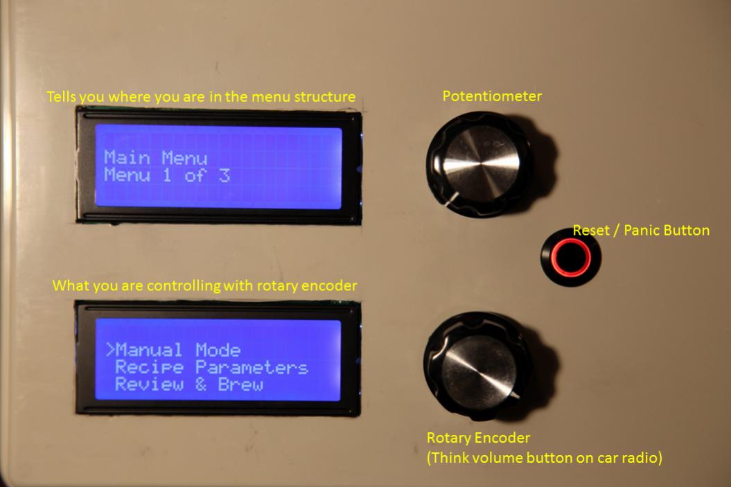
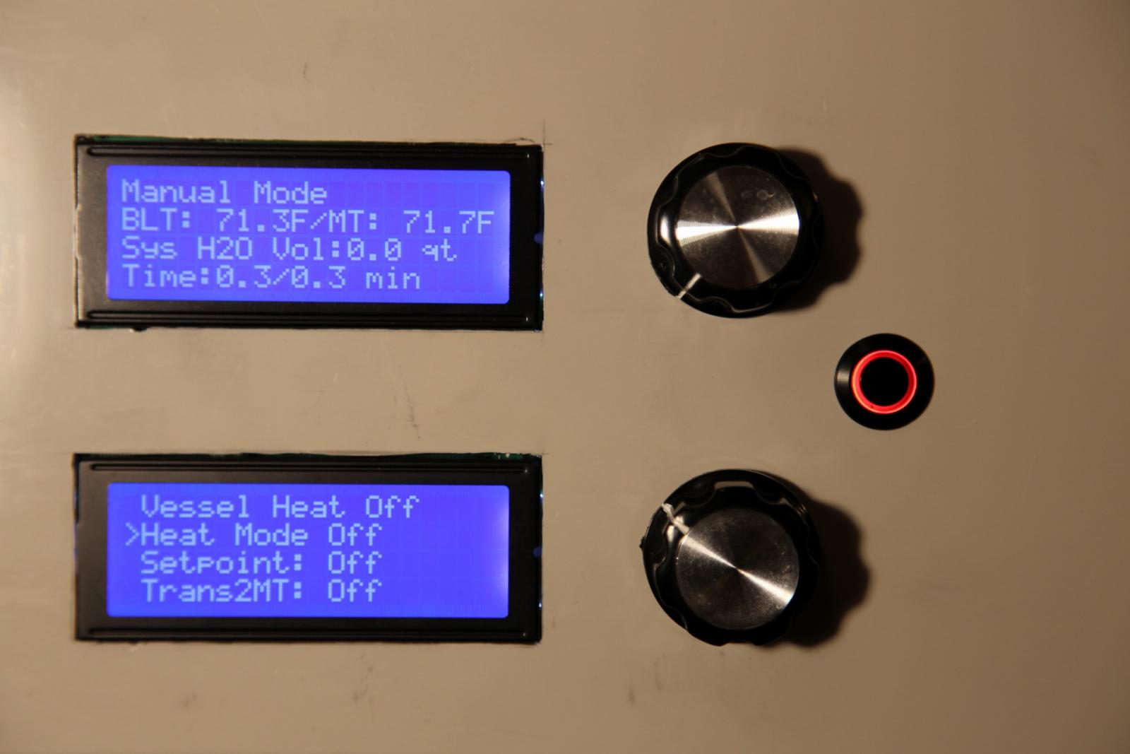
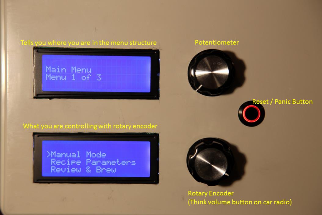
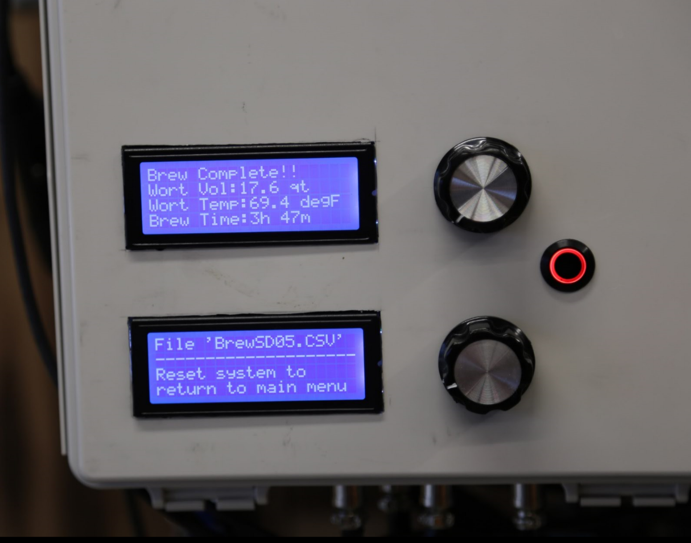
Yes. See attached Pictures. I don't know of a great way to add a video to this thread so you're just going to have to take my word that the rotary encoder is a fairly efficient way to interact with the controller.

Top LCD
Prior to brewing, primarily used to help me understand where I am in the menu structure.
Once brew session has begun, displays primarily information about the status of the overall brew session (time remaining, time elapsed, total water volume ingested, etc..)

Bottom LCD
Prior to brewing, what you pay attention to when navigating & changing variables for the recipe.
Once brew session has begun, displays pertinent information to current process (target & actual vessel volumes. temperatures, etc)

Rotary Encoder
Prior to brewing, how you interact with the system. So far I haven't found a use for this once the brewing session has started (automated system..)

Potentiometer
Currently only utilized during Boil AFTER hot break. During Hot break the heating element duty cycle is set to 100%. Once a certain amount of time has passed (xx minutes) duty cycle will change to whatever the potentiometer is set to.

Reset / Panic Button
It is truly just a reset button but the very first thing my code does is shut down all pumps & close all valves. So it is a 2-4-1 deal.


Menu Structure
The picture with the black background shows an outdated version of the menu structure. This is just to give you a feel for overall structure of the interface. The orange/tan boxes have been changed several times in my code since I last updated this graphic.


Would love to see your code as I'm not well versed in Arduino code, just played around a bit.

Once I have a few brews under my belt I will find a way to post the code.

Main Menu.jpg


20170906050552_IMG_7163.jpg


20170906050653_IMG_7165.jpg


Old Process.JPG
 
Will you have a HMI Screen for recipe setup and HOA control?

I don't know of a great way to add a video to this thread so you're just going to have to take my word that the rotary encoder is a fairly efficient way to interact with the controller.

Okay... So I was trying to add a post with a 3d PDF and realized I could post a *.mov file.

Attached is a short vid of me with the user interface.

Quick press of the button = Select
Hold button for 350 milliseconds = Exit/Return

View attachment MVI_7166.MOV
 
It is a novel approach, using two HEX's. Kind of like external HERMS.

I was going down a more traditional path until I received two heat exchangers for the price of one (cosmetic shipping damage to first). I couldn't let it go to waste so I found a way to use both.
 
Kick me later but what does "BCS" stand for?
http://www.embeddedcc.com

I am using a relatively inexpensive pressure sensor to predict water volume. The proof of concept is shown in posts 25 & 30 from linked thread.

https://www.homebrewtalk.com/showthread.php?t=591727&page=3


Do you have a thread somewhere to show your system? I am curious.


RIMS via plate heat exchanger. I'll show this in detail at a later time.


Will be a garage queen. I haven't started on ventilation yet but I will need it.


I used the Arduino IDE to write my programming. I used a fair number of libraries from the webs in my code.


Sorry for the late reply, working on moving.

BCS = Brewery Control System http://www.embeddedcc.com

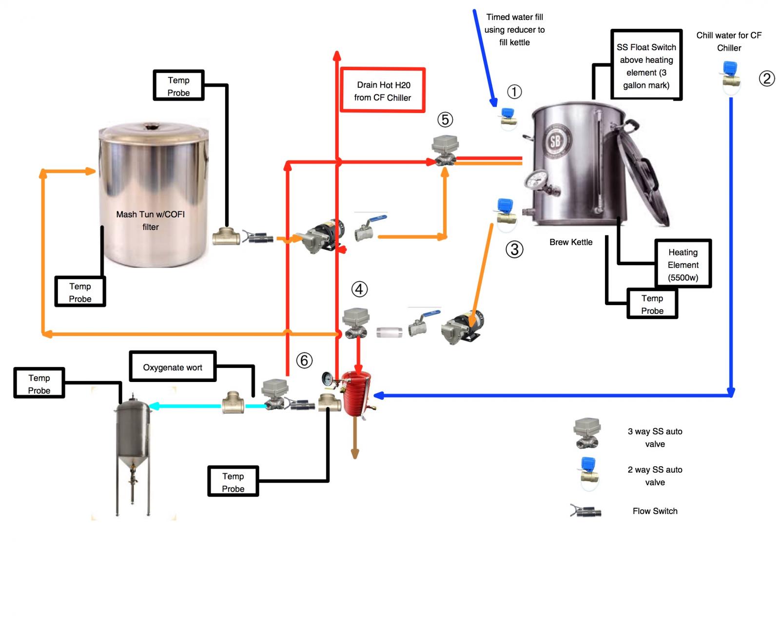
No thread but here is an image of my layout.

NoSpargeBrewSystemV2.jpg
 
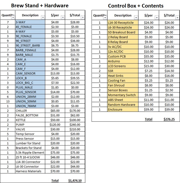
This is pretty close to capturing the big ticket items and incidentals.

Total cost came in around $1,750. After I add in parts for automated boil additions we could probably round up to $1,800.

Note that $360 was just for stainless fittings. Of that ~$111 was for camlock fittings to make this a modular system. This makes it easier to break down for cleaning/storage.

Ended up about $500 more than I expected for the overall cost but I am still pretty happy with the results. It has been a rewarding experience and I have learned A LOT (understatement!).

BOM.jpg
 
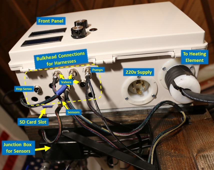
More details on the electrical hardware.

What is not obvious in the pictures is the purple PCB is a shield which sits on top of an Arduino Mega. The purple PCB just gives me a one-stop-shop to hook up everything that requires logic to operate.

You might notice the SSVR is NOT connected in the picture. This is a place holder for now. If I can't manage acceptable control of the boil I will put the SSVR in series with SSR1 to control heating element duty cycle via voltage regulation instead of modulating the element on/off with the SSR's. This will required an additional potentiometer controlled by a servo inside of the enclosure to automate the voltage regulation.

Cheers!

Main Menu.jpg


Enclosure Exterior.jpg


Enclosure Internals.jpg


Custom PCB Diagram.jpg
 
Tell us more about the hop servo!

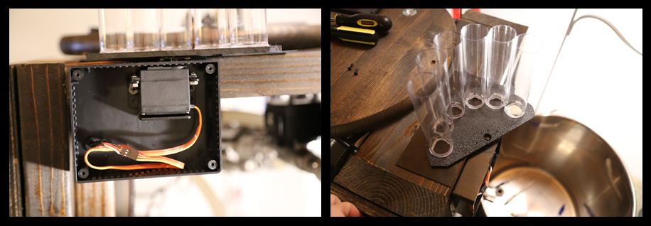
Same basic concept as Hops-Boss (check youtube). I will use a servo at the center of rotation instead of a stepper/DC motor at the perimeter. Mine will be mounted to the brew stand instead of the kettle.

Anticipated BOM
Scraps of ABS sheet: $5?
ABS box to keep steam from servo: $5
Servo: $10
Plastic Vials to hold hops: $12 (for 15, only need 6) (some PVC from the local hardware store would be cheaper...)

Vials arrive tomorrow and I'll try to get it built/post pics before the work week sets in.
 
Looks very interesting.
How much disassembly/reassembly is required for cleanup? How much cleanup automation is possible?
 
Welp.. It worked almost as intended on its first brew last weekend. It was hands off until the hot break when I manually controlled the heater duty cycle to avoid a boil over. After I get a few brews under my belt I should have enough data collected to automate the heat coil duty cycle during hot break & boil.

Also, hops stuck in the hop dropper. Have a couple solutions to try and pretty sure I can correct that issue in the next 1-2 brew sessions.

I was not able to confirm the final accuracy of the Wort volume this time since I was a bit rushed to get everything cleaned up on a Sunday night. Another thing to verify on a future brew session.

Hopefully in the next few weeks I will be able to finish out this build thread with its performance and what is inside of this system to help future would be automators with some ideas of how they could do it.

Capture.PNG
 
Looks very interesting.
How much disassembly/reassembly is required for cleanup? How much cleanup automation is possible?

Cleaning is basically:
  • 2x cycles of fill/circulate/purge
  • a 3rd cycle with some PBW (I actually use Oxi-clean free)
  • then a 4th cycle to flush out the Oxi-clean (and 5th if needed).
On the 3rd cycle I heat the system up a bit and get a clean cloth in the BK to break away the stubborn stuff and clean the heating element.

I feel like I can be pretty effective at cleaning it in place but so far I have taken it apart to allow the kettles to air dry upside down. I didn't think of it so far but I guess I could towel it dry and leave everything hooked up in the future..?

I use a coarse bag for the grain so I take that out and dump it in the garden during the boil. If I stop bagging the grains in the future I am able to remove the MT (2x camlocks) and hose it out during the boil if needed.

I also use a hop spider so I just hose it off in the yard.

I'll take some pics in a future brew but clean-up was painless. Time will tell if my heat exchangers are as clean as I hope they are :yes:. I think I will be able to automate a cleaning cycle with exception of the part where I scrub a bit during the 3rd fill/rinse cycle.
 
Very curious how to built the custom PCB? I’m looking to do something similar but need to learn more about the process. Any guidance would be appreciated. I run a single element 2 pump 2 vessel no sparge setup.
 
Very curious how to built the custom PCB? I’m looking to do something similar but need to learn more about the process. Any guidance would be appreciated. I run a single element 2 pump 2 vessel no sparge setup.

I'll assume you are already using a controller of some type and know how to connect/control other stuff (relays/etc) from it.

To be transparent I am a complete hack. See those capacitors in that board above.. No idea if they were necessary or even helpful but everywhere I looked people said to have capacitors when using IC's.
I have designed/built 3x PCBs. All 3 worked as desired but I had to do a couple unplanned jumpers due to poor execution of step 4. Overall it is pretty straight forward. Just takes a little more planning.

General steps to success:
Step 1: Mock up your project using a breadboard and make it work!
Step 2: Find some software to design your PCB (I used Fritzing but don't have a good reason for that selection. there are other choices)
Step 3: Design your PCB based on the working prototype from step 1
  • Fritzing has the arduino boards pre-loaded so designing a shield to sit on top is trivial
Step 4: Check & re-check the PCB design. Specifically make sure software makes all the connections to ground as expected.
Step 5: Order from where ever. I used Fritzing's service early on. It was easy but not cheap. I used OHS for this last one and it was good service.
Step 6: To avoid any surprises, take 10 minutes and verify all your connections are correct with a multi-meter. MUCH easier to do now vs later.
Step 7: Transfer parts from your breadboard mock-up to the PCB and solder. Take care as you can paint yourself in a corner if you don't plan which components to put in first.
 
Code:
//Libraries
  #include <OneWire.h>            //Enables use of one wire temperature sensors
  #include <DallasTemperature.h>  //Enables support of specific Dallas temperature sensors
  #include <SPI.h>                //Needed to communicate with data logger
  #include <Wire.h>               //Needed to communicate with data logger & I2C LCD
  #include <SD.h>                 //Needed to write to SD card
  #include <Servo.h>              //Servo library. Servo will control hop additions
  #include <LiquidCrystal_I2C.h>  //I2C LCD Librarry
  #include "Tlc5940.h"            //Library for TLC5940
 
Back
Top