Automated LODO Build

Homebrew Talk - Beer, Wine, Mead, & Cider Brewing Discussion Forum

Help Support Homebrew Talk - Beer, Wine, Mead, & Cider Brewing Discussion Forum:

This site may earn a commission from merchant affiliate links, including eBay, Amazon, and others.
IMG_0121.JPG
Rodi to be installed...
IMG_0122.JPG
Water softener for the rig.
3.JPG
My tig gloves after 3 months of use, bought the same pair again.
4.JPG
Tune in next time the kettles should be finished pretty quick and I should be onto to pipe-work.
5.JPG
Thanks everybody.
 
That is a pretty cool thing you're doing. How much LODO brewing did you do before getting into this new project?
 
That is a pretty cool thing you're doing. How much LODO brewing did you do before getting into this new project?

Not a lot. I don't use any oxygen scavenging chemicals so technically probably none. This kind of build not needing any additives to be lodo is what convinced me to build it. I was already going to build a cool automated rig, really not that much further to make it lodo (pressure tops, gas, DO sensors, and a pre-boil CFC).
 
That is a pretty cool thing you're doing. How much LODO brewing did you do before getting into this new project?

Not to rag on Overkill but to add to the whole ambitiousness and insanity of this build: this project was started after having done exactly one brew, about a month after leaning the basics of how brewing works.

I have never seen anyone dive so balls-deep into a hobby so quickly as Overkill
 
Damn, you did a crapton of work!! looks great!! must have gone through a ton of argon!
 
Damn, you did a crapton of work!! looks great!! must have gone through a ton of argon!
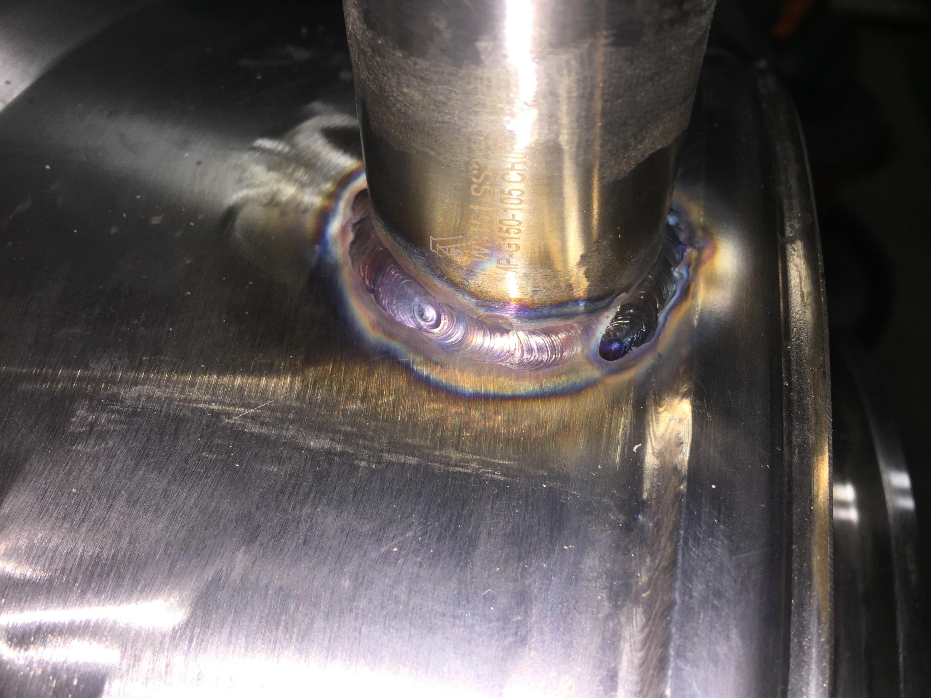
On my 3rd tank now. Should have enough left to finish the last kettle (the BK, mash tun and hlt pretty much completed) and will need probably one more for the pipe work. I also ate a tank of helium tri-mix for the mig work but have some left.
 
No disrespect, some captivating work being done here, but you should check out Die_Beerery's rig if you want to see someone truly playing at the extreme fringe of "home brewing"...

Cheers! :)
I know his posts well. His posts inspired me to start this project about 6 months ago once i saw what was possible. This is a near total clone of his rig, down to the same part numbers on all the electronics / pieces of equipment. Main difference is I'm building the kettles from scratch. His were manufactured by stout. But all the kettles have the same number of ports, DO probes, ph, flow sensors, pressure, nitrogen purging, CIP cleaning, pumps, valves, controllers, software interface, etc. This will be a fully automated computer controlled, scripted/program run system. Once the pipe work is started and the kettles get buffed out it will start to look pretty insane. You get some idea...
IMG_0516.JPG
 
Been busy. Kettles are finished. Couple shots of the build...this is the hole for the tangential whirlpool return on the BK.You can see nothing on the BK as really done yet. I used a die grinder to cut this. Drilled the bottom ports also. Trub dump main drain in center, and a port as far to the side as possible for finished beer out.
1.JPG
3/4 inch SS pipe. ID is about .55 i believe. I cut some of it off to minimize grinding after the weld.
2.JPG
Fit up is ok could be better.
3.JPG
Completed weld. Used a heavier filler as there were some gaps to fill. Getting good fit-up on tangential port is hard.
4.JPG

Closer shot.
5.JPG

Turned out pretty nice.
6.JPG

It's gona work great.
7.JPG
Inside after grind down. Very flush / sanitary.
8.JPG

Close up.
9.JPG
 
Couple pics showing the installation of an inside/outside port. Useful in connecting things like HERMS coils or CIP balls, sparge arms, etc. The mash tun had 4 and every kettle has a few. This if the weld where I first welded the inside flange.
1.JPG
More weld porn.
2.JPG

even more...
3.JPG
And now the outside flange is sanitary welded to the inside flange. No filler is used.Good fit up is critical.
5.JPG
Inside the coupling you can see minimal crevasses due to no filler being used.
6.JPG
Turned out nice. You can the the next one on the other side too.
7.JPG
 

Attachments

  • 4.JPG
    4.JPG
    2.2 MB · Views: 176
Mocking up the BK trub damn on the bottom of another cut up keg. Red sharpie hole is the BK clean beer out. I cut the damn from some spare steel I had from one of the keg rims.
1.JPG
Damn in BK getting fit up. You can see the main trub out port before grinding as well.
2.JPG
Trub damn installed. I welded a bunch of pins in and drilled some holes in the damn so its slides in and out and is removable now. You can see the pins. Fits snug and turned out nicer than I expected. Also you can now see the same trub out post grind down.
3.JPG
Let's install at 3750 Blichman boilcoil. Also you will see by now i have welded on a TC port to the tangential port pipe
1.JPG
Boilcoil inside. This was more annoying to install then I thought.
3.JPG
View of her test plugged in.
4.JPG
3 finished kettles with lids.You can see I already started polishing the BK a bit.
5.JPG
 

Attachments

  • 2.JPG
    2.JPG
    1.1 MB · Views: 78
Bit of the polish process. I am using a 6 inch sisal wheel from caswell plating and a few of their buffing compounds. Seconds with the wheel turns years of faded metal into a shine. BTW this stuff is horridly nasty. Respirator is a must and a full face shield. Parts are flying at you the whole time. It ruins your clothes and when you're finished it looks like you just swept a chimney. And it covers everything in the room in black compounding dust. Def the grossest part of this project.
1.JPG
Some close ups of the top.
2.JPG
dito...
3.JPG
Polishes weld joints really nice also.
4.JPG
 
Finished BK.
1.JPG
Finished MT.
2.JPG
MT close up.
3.JPG
HLT also has a tangetial installed just as the BK does.
4.JPG
Another MT shot.
5.JPG
All 3.
6.JPG
BK with tangential.
7.JPG
Bottom plumbing configuration.
8.JPG
Top view.
9.JPG
Close up to on HLT.
10.JPG
 
Ok so up until this point I actually didn't have my castors installed. This is trickier than it sounds. I wanted to be able to move the rig, but also height adjust each leg level. I ordered some thick SS plate to fabricate the wheel mounts to the bottom of the legs.
1.JPG
Plates prepped for welding. I drilled holes to bolt the wheels on. I needed to be careful during the weld not to weld over the holes even slightly.
2.JPG
Fit up and tacked in place. I tacked them up-side down and then welded in final orientation as welding above head is hard af.
3.JPG
MIG welded. Was cool to fire up the wire feeder again.
4.JPG
With wheels bolted on. These were from amazon if anyone wants the make I can find it.They are quality and a pack of 4 was like 30-40 bucks.
5.JPG
 
Had to mix things up a bit. Bought a chronical fermenter and needed a glycol chiller. Had this 12000 BTU window AC in my garage from a few years ago, and since I now have central air, lets do a chiller build. It's a beast.
1.JPG
Mounted it to a piece of heavy plywood on some small castors.
2.JPG
new chronocal mock up...
3.JPG
Ordered this cooler on amazon. there will be 17 gallons of glycol in here to cover the coil. Now I wish i went with a smaller unit as 6 gallons of glycol to make 17 gallons final diluted is like 150 usd. ouch.
4.jpg
Plumbing in/out install. I replaced the thermistor the AC came with for a lower resistance 3k ohm thermistor (installed with a thermowell to the right). This tricks the unit into thinking it's hotter than it is. A thermistor resistance table can be use to calculate what temperature the unit thinks it is vs what it really is. Very simple solution compared to gutting the internals of the machine.
5.JPG
Still need to encase it but it works great. Already made a few batches using the unit.
6.JPG
 
Ok, kettles are done. Let's plumb. First thing is to get the Micro Motion Mass Flow Meters into position. As I talked about in an earlier post, they came with flang connections. All my plumbing will be TC, so we need to go from industrial flange to TC. Welding can solve this problem.
1.jpg
Fit up is good...
2.jpg
Top view. I'm going to weld this on the outside and inside.
3.jpg
And here we are on the outside. Easy.
4.jpg
After cleanup with a brush.
5.jpg
Inside before the weld.
6.jpg
Inside after the weld.
7.jpg
After a little grinding, bolted onto the MFM. There is a gasket you can't see in between the flanges. This is extremely tight and there is zero give/wiggle in this joint.
8.jpg
Both sides bolted on and mock up in position. I'm still not 100% on if I should mount them like this or flip them 180 and mount them upright by fastening them to the lower rig support. This orientation is easier to install, but the other orientation allows for the MFM to drain when not in use. Which I like.
9.jpg
Top shot... either orientation these will fit great.
10.jpg
 
Close up...
11.jpg
Side view. You get an idea of how i am planning to mount them using a hinged pipe hanger and mount. No force can be applied to the box, so the weight myst be on the pipe or flanges. Going to weld a SS threaded mount to support the MFMs. Need to order it in SS as this one is zinc.
12.jpg
Back one...
13.jpg
Close up of internals. Nice joint.
14.jpg
The second one is in that box to the right but you get the idea. I'm still waiting on TC to NTP adapters purchased in bulk to arrive from china so that I can mount the electronic ball valves.I need all the parts of a connection before i can weld anything regarding the plumbing, so until these stupid adapters arrive i'm stuck.But you get the idea.
15.jpg
Better shot of how I plan to mount the MFMs. There will be a threaded post connecting them supporting the weight.
16.jpg
Pipe hanger shot.
17.jpg
Things to come for next time. 40 elbows. I hope it's enough it may not be.
18.jpg
 
And some random shots I thought were interesting. Here is a situation where I forgot to install the purge box during a weld. Was busting so many of these out that it just slipped my mind. Realized about 3/4 of the way around what I had done. Luckily it was a 1" fitting so I cut it out using a 1.5" hole saw bit and installed a 1.5" furrel in the same spot instead. But you can see the extreme sugaring that happens on thin stainless if you don't purge. It's gross. Always purge.
1.JPG
2.JPG
Oh and wear a face shield when operating an angle grinder. This disk exploded on me and I was glad to be wearing it when its shard hit my mask. It's rare but it happens. Next posts will be the plumbing, and it will be time for electrical and programing.
3.JPG
 
It's been a while since i updated this. Been busy with other projects and traveling, and had to wait on a lot of parts I ordered to arrive. I welded a cut up threaded C-clamp to the frame where the MFMs will go to support them properly.
1.JPG
Threaded bolts are height adjustable to support the pipe clamps/ fittings to hold up the MFMs without damaging them.
2.JPG

These are the sole contact points for the MFMs holding all their weight.
3.JPG
4.JPG
Counter flow chiller from Stout finally arrived after a few moths. Nice build quality. Much larger and heavier than expected. This is going to chill wort in the BK during cooling recirculation.
6.JPG

Examples of some parts I was waiting on from china. In order to finish a connection from point A to B in the plumbing, I need all the parts to make sure there are no gaps. So it's slow going.
7.JPG
 

Attachments

  • 5.JPG
    5.JPG
    1.1 MB · Views: 95
Starting to connect the HLT to the MT.
1.JPG
This is the return from the herms coil headed back to the MT.
2.JPG
At this point i realized i needed Ts. So, a month we wait.
3.JPG
4.JPG
Ts finally arrived, can continue. This gap on the left is going to need a custom part fitted / welded.
5.JPG
6.JPG

Fabrication of the gap joining part post tack and argon purging.
7.JPG
 
Fabrication of a custom spool for gap junction.
1.JPG
Inside look, pretty smooth, sanitary weld.
2.JPG
Some of my nicer work.
3.JPG
4.JPG
Final product. 2 custom parts were made for this connection.
5.JPG
Turned out pretty nice.
6.JPG
Temperature probe up top comes down exactly to the center of the cross. This will be the HERMs regulating temp probe.
7.JPG
 
Sight glass. I like this one, purchased from ebay. Will get a second for the BK recirc loop also.
1.JPG
Need to join this gap from the sight-glass to the MFM.
2.JPG
Custom part half fabricated.
3.JPG
Different angle.
4.JPG
Elbow cut a fit up.
5.JPG
Completed part post weld.
6.JPG
Rig so far.
7.JPG
8.JPG
9.JPG
And so it goes slowly. I'm hoping that since a bunch of parts now arrived I can speed things up a bit. I still am waiting on some proportional valves to arrive though, so until those get here I can't do some of the under workings. But definitely enough to do before they arrive. Headed to hawaii and japan in 2 weeks and am hoping to have all parts here once i get back. Will update as soon as possible but it's starting to come together.
 
Overkill is definitely the most appropriate username ever. This is a great thread, keep the posts coming!
 
Nice continued work... One thing though, generally best practice when you reduce from a larger size sanitary fitting to a smaller size fitting, you want to use a reducing adapter of some sort (even if the mating flanges are the same as your 1.5" to connections 1" for instance).

:mug:
 
Nice continued work... One thing though, generally best practice when you reduce from a larger size sanitary fitting to a smaller size fitting, you want to use a reducing adapter of some sort (even if the mating flanges are the same as your 1.5" to connections 1" for instance).

:mug:
That is true. It's easier to ignore this fact though. Most of my plumbing is 1", but there will be probably 10 instances of 1.5 to 1. I could insert reducers, just unsure if the performance gain will be negligible related to the trouble. I will consider it more seriously though going forward.
 
I just thought I would mention it as you're putting so much effort in to this build; I wanted to make sure you knew this.

Performance wise I think you'll be fine-- my understanding is this practice is for things to be considered truly sanitary. But since this is all hot side, you should be more than okay.

:mug:
 
I'm fascinated by this thread. @Overkill, do you have an update?
I’ll post one soon. Had a lot of other stuff going on the last few months but I’ll make an update soon. I expect the build to be done by summer which is a lot longer then I originally planned. But it’s coming.
 
Just went through all of the pictures. Wow, just Wow, that's all I can say.

How much has been spent on all of the components, gas, welding equip etc.. up to this point if you don't mind me asking?
 
Just went through all of the pictures. Wow, just Wow, that's all I can say.

How much has been spent on all of the components, gas, welding equip etc.. up to this point if you don't mind me asking?
lol god know's how much. Honestly i lost count because its spread out over 1.3 years now but if i had to guess probably 8K.

Welding equipment (gas, tanks) ~2500
steel and pipe~1200
Random TC fittings ordered from china ~1000-2000
MFMs 600 for 2
random control boxes, random parts 1000
buffing equipment 3-500
random tools, saws, drill presses, grinders...1500
pressure sensors 600
valves 600
electrical -1000


A lot. Def more than 5k, but probably less than 10K. Maybe 10. Probably another 2K of ******** will end up in it before its completely finished. I've spend more money on dumber ****. This is one of those it's more about climbing the mountain things than getting to the top. If you just want a brewery you could probably buy a several BBL pilot batch commercial unit for what i'll end up putting into this by the time it's finished. This should be a bit more automated tho. Also somehow every-time I go to homed-depot or order parts its 3-500 that disappears like a fart in the wind. But that depends also on if you count tools, i basically built a small welding shop to do this. It's not the only project i've used it for or will use it for.

My main enemy is time. Lots of other projects going on and you can only focus on so many things at once.

Die Beerery's thread is also worth checking out he's using more commercially available parts. If you just want one up and running in under a year (still a mountain of work to program and assemble) i'd buy what he has. Although I think you'll still be around 10K with his system at least. Maybe 15.


....never realized this thing changes swear words to pg ones before.
 
I am a big DIYer myself. Its awesome that you are sharing your build. The cost is lower then I thought. I am interested to see your finished system and hear how the beer turns out once you get a few batches in and get the process nailed down.
 

Latest posts

Back
Top