Automated Brewery Valve Layout Diagrams

Homebrew Talk - Beer, Wine, Mead, & Cider Brewing Discussion Forum

Help Support Homebrew Talk - Beer, Wine, Mead, & Cider Brewing Discussion Forum:

This site may earn a commission from merchant affiliate links, including eBay, Amazon, and others.

Squeeky

Well-Known Member
Joined
Sep 29, 2005
Messages
447
Reaction score
19
Location
Dayton
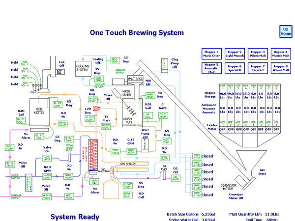
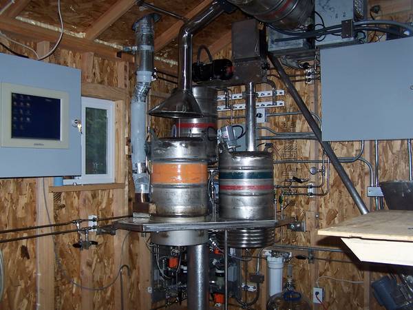
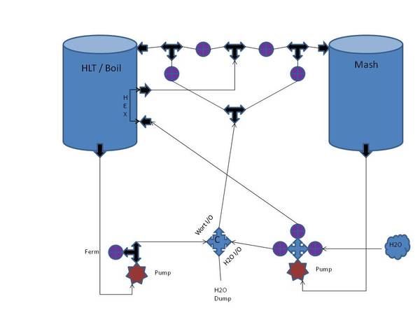
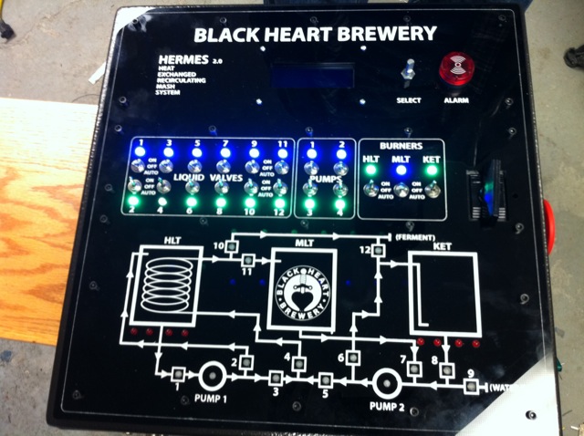
One of the fun aspects of automation is designing your valves and flow diagrams. I would like to start a thread should valve layouts and system designs. If you have any to contribute please do so. All that I will post are references to ones I have found online. I am currently in design phase of my own system just gathering parts.

13.JPG


Brewery20.jpg


17795d1289104347-single-tier-3-pump-bcs-462-automated-rig-brew-rig-v10.jpg


http://www.brewtroller.com/downloads/btbrew.pdf
 
This is what I was using at one point, I've since changed but perhaps it could help others...

Valves.jpg
 
I kind of like this one....lol.

I modified this layout to T the therminator output back into the BK return. That way I can do a chill/recirc back to the kettle before going to the fermenter. If your ground water is cold enough (mine isn't) you might be able to go straight to the fermenter in one pass of the chiller.

Are you planning on doing HERMS or RIMS?
 
My current setup is herms three vessel, but I'm seriously considering two vessel. I'm using a BT3.3, due to pressure sensors for volume. I have 12 valves at my disposal and want to make a system that also controls water in.

In a dream world I would make the Control panel 120v, and the 240v power a module box. So that if I wanted I could run same control panel on kitchen setup for small test batches. Then go to a 55 gal setup when I win lottery :).

Due to budget I'm looking to keep at 2 pumps but might increase then with DC solar pumps for better flow control during sparge.
 
Here is the latest overview for my system currently under build. Uses 4 solenoid valves for tap or RO water and 7 automated ball valves. I am assisted by the pumps as they are peristaltic and essentially act as closed valves when not running.

HERMS_Plumbing_V_10.PNG
 
Here are Visio diagrams of my valve setup along with a pic of the actual plumbing. Right now, the valves are manual, but will be replaced in time with automated valves.

mainmanifold.png

wortpump.png

waterpump.png

plumbing.jpg
 
Here is the very simple schematic that is on my control panel. This is for a RIMs System controlled by Brewtroller. I also have views that show the LED status for each Brewtroller valve profile I can add in too.

Picture1.jpg
 
Hi Squeeky, nice to see you here again!

As you should remember my HERMS bt powered system is under heavy build, I hope to complete and test it in less than a couple of weeks.

this is my flows schema

phase1.002.png


10 motorized valves (7 two ways and 3 three ways) and two March pumps.

That means a lot of wires and connectors to weld! :)

My setup with all the different phases: https://www.homebrewtalk.com/f51/myherms-project-293873/

cheers


gm
 
Kladue,

Just wanted to say . . . Speechless.

Crazy DIY automation setup, I tip my brewing hat.
 
What actuated valves are you all using? I am looking at doing a similar setup to some of these and am trying to source decent 3 way, stainless, actuated ball valves at a reasonable cost (<$100). The only ones I seem to be able to find are these:
http://www.oscsys.com/3-Way-Motorized-Ball-Valve.html

I am not particularly wild about this choice because the threads are BSP and the voltage is 12V. I would much prefer NPT and 24V. I doubt there is anything affordable out there but my ideal valve would be a 1/2" actuated sanitary ball valve. Know of anything?
 
Nope that is likely the best deal on 3-ways. I checked into them from the company I got my 2-ways from and they do not make SS versions. The KLD brand ones OSCSYS sells are quality. Plus I doubt you would notice much a difference from BSP and NPT if using silicone tape.
 
ok Kladue... there's so much stuff there, where is the 'one touch'

Seen this before. Simply incredible!
 
Once the malt is in the hopper, hop bags are hung, fermenter connected, you hit autorun icon on touch screen and walk away. It is the automated version of the original flash boiler brewing system, and was designed to let me do other brewery chores while it was doing the brewing. The only items that are not shelf items are the flash boiler fittings (swagelok cap and cross welded together and drilled), and the screen in the steam into wort diffuser.
 
OK.KLD valves it is then. Do you really think you can get away with NPT male on BSP female? For some reason, I kind of doubt it... I'm going to try to source some BSPxSanitary fittings. BTW, since this is more of a schematic thread, here is my schematic. Boxes represent digital outputs/inputs (DO/DI) or analog outputs/inputs (AO/AI). Box w/ circle leading to burner represents Honeywell furnace valve...

Before I commence with purchasing... feedback would be greatly appreciated!

Kladue, I know you seem to be the expert on the Honeywell gas valve stuff... Does what I have look reasonable. From the propane, the first regulator should drop the pressure down to 10psi and the second should drop down to the low pressure (1/2 psi). From there the gas line branches 3 ways... Each path has a Honeywell VR8200 as well as a manual control valve. The burners are 23 tip jet burners. Any comments would be greatly appreciated.

Thanks!

Process_Diagram_3.jpg
 
Oh a couple more clarifying comments:
-valves w/ box and "M" are motorized, valves w/ out are manual.
-box after water supply "from hose" is plate heat exchanger and inlet/outlet are opposite corners.
 
Ok, have you checked with brewers hardware? they might be able to weld up a 1/2" BSP pipe nipple into a tri-clover flange to make it work. The gas diagram looks right, but I would strongly advise against using jet burners, use the 10" banjo burners and save the grief of trying to make the jet burners work. Buy 10" (BG-14)for HLT and BK, and a 6" (BG-12) for the mash tun, and source the low pressure jets from One Hoppy Guy. This has proven to be the best setup for low pressure propane around, jet burners have not worked all that well because of the design and construction flaws, and most have gone on to the banjo burners.
 
I would agree with you on the NPT versus BSP issue except on 1/2" plumbing. For 1/2" size, the threads match up very well. There are many people using them without issue. These are not high pressure systems.
 
1/2" NPT will go about 3/4-1 turn into a BSP threaded fitting and get tight because thread pitch is different, better to get the correct threads than force it and have it gall up and ruin both the male and female threads. Working with internationally manufactured devices I am quite familiar with what works and what does not when it comes to threaded connections. If you can not get a custom fitting then an adapter from BSPT to NPT will solve the problem.
 
Huh. Good to know about the BSP to NPT. I will give it a shot. Is Brewers Hardware the best source for NPTxTri Flange?

Kladue- thanks for the pointer on the burners... It's a shame because those jet burners look so damn cool when they are all fired up! I suppose it's best to do what is proven to work though. As far as ordering the VR8200 gas valves, what do they come with and what will I still need to purchase? Do they come with the pilot compression fitting and tubing? I assume they do not come with the pilot burner? What about the thermocouple or whatever it is they use to verify the pilot is lit?

Thanks in advance.
 
Oh... Ok, just saw your post Kladue... That is what I am thinking too... I have had a lot of bad experiences with stainless gauling.. the last thing I want to do is ruin my valve body at $80 a pop... I found these guys:

http://www.mfgaa.com/triclamps.html

Looks like they can do it, its just a matter of cost. I'm going to inquire about it.
 
Hmmm... if the pitch is the same... I guess it could work... I'm going to get a price on the correct (BSP to Sanitary fitting). If it is around the same, I will most likely do that. If it is much more, I will try the NPT right into the BSP.
 
The gas diagram looks right, but I would strongly advise against using jet burners, use the 10" banjo burners and save the grief of trying to make the jet burners work. Buy 10" (BG-14)for HLT and BK, and a 6" (BG-12) for the mash tun, and source the low pressure jets from One Hoppy Guy. This has proven to be the best setup for low pressure propane around, jet burners have not worked all that well because of the design and construction flaws, and most have gone on to the banjo burners.

Wait, so source the low pressure jets meaning the entire burner from One Hoppy Guy? Does he sell these or something? Also, are there both low pressure and high pressure BG-14/BG-12? I want to make sure I don't order the wrong thing.
 
For the burners look here http://www.agrisupply.com/cooking-supplies-utensils-kitchen-accessories/c/5400000/, for the conversion to low pressure gas jets check with these folks http://brewsteel.com/, and finally the gas valves can be sourced from PEX supply, a VR 8200 valve http://www.pexsupply.com/Honeywell-VR8200A2132-1-2-24-Vac-Standing-Pilot-Gas-Valve-11588000-p, Q314 pilot http://www.pexsupply.com/Honeywell-Q314A4586-Honeywell-Q314A4586-Pilot-Burner-4113000-p, and thermocouple http://www.pexsupply.com/Honeywell-Q390A1046-24-Thermocouple-1721000-p. To power the valves you will need a 120/24VAC transformer like this http://www.pexsupply.com/Honeywell-AT175A1008-Foot-mounted-120-208-240-Vac-Transformer-w-9-in-Lead-Wires-75VA-11016000-p. To connect the pilot burner to the valve, 1/4" soft copper from the big box building supply house or from hardware stores will work.
 
Wait, so source the low pressure jets meaning the entire burner from One Hoppy Guy? Does he sell these or something? Also, are there both low pressure and high pressure BG-14/BG-12? I want to make sure I don't order the wrong thing.

You will need to drill them out to .073” / #49 for low pressure. We don't sell burners.

+1 on PexSupply, we buy all our gas components from them
 
The burner castings work with either high or low pressure, the difference is in the brass gas jet fitting. Brewers supply is a source for the BG-14 low pressure jets http://www.brewershardware.com/Valve-and-LPG-Orifice-for-BURN10.html, the BG-12 is a DIY with #45 drill bit, or sourced from Bayou Classic http://bayouclassicdepot.com/615-control-valve-brass-fitting.htm. To feed the gas valves a marshal 290 series 2 stage regulator and Green tank adapter http://www.americanrvcompany.com/Camco-59923-Propane-Acme-Nut-Green-Grill-Camper-Trailer-RV_p_5893.html will work nicely
 
Last edited by a moderator:
Thanks. Is the purpose of the orifices purely for flow restriction to get a good flame? The regulator should drop down to the correct delivery pressure and the orifice basically sets the flow? If this is the case, wouldn't I want one orifice per burner and why would you want an orifice at the propane tank?

Correct me if I am wrong. For my low pressure LP system w/ Honeywell control valves, I will need the following (starting at tank and in direction of flow):

(1) LP Tank
(2) Regulator in the 0-30psi range w/ hose
(3) Secondary regulator to the 11"WC range
(4) Isolation valve
(5) Honeywell VR8200 (1 per branch)
(6) Flow Control Valve (1 per branch)
(7) Orifice Connector (1 per branch)
(8) Burner (1 per branch)

Does this seem right?
 
Hey Chris,
Interesting blog! Seems lk you know a lot on breweries.

If so could you help answer few of these questions. Its for a research project.

Q1: How much water is consumed in a brewery every day/every hour?
Q2: What is the inlet / outlet pressure of water (hourly/daily)?
Q3: Do breweries use Pressure Reduction Valves ifor water operations?
Q4: If so, How much are do they reduce pressure by, in feet or PSI?
Q5: What is the entry and exit point of the water?

Would appreciate if you could try and help me out since you know a lot bout breweries!

Thanks!
binson
 
Thanks. Is the purpose of the orifices purely for flow restriction to get a good flame? The regulator should drop down to the correct delivery pressure and the orifice basically sets the flow? If this is the case, wouldn't I want one orifice per burner and why would you want an orifice at the propane tank?

Correct me if I am wrong. For my low pressure LP system w/ Honeywell control valves, I will need the following (starting at tank and in direction of flow):

(1) LP Tank
(2) Regulator in the 0-30psi range w/ hose
(3) Secondary regulator to the 11"WC range
(4) Isolation valve
(5) Honeywell VR8200 (1 per branch)
(6) Flow Control Valve (1 per branch)
(7) Orifice Connector (1 per branch)
(8) Burner (1 per branch)

Does this seem right?


If all burners are low pressure, you only need a low pressure regulator.
Isolation valve?
Items 5 through 8 are correct. (use needle valves)
 
Updated my project, saving one 2 way valve and now being able to properly clean with water both the pumps, the cooler and the herms coil

MyHerms%20V2.001.jpg


Here my project thread.


cheers


gm
 
hmm... looks like someone has controls and instrumentation experience
they look just as good as the professional drawings I've worked with
 
So I have 3 little pumps from greatbreweh.com, 2 ifm flowmeters (eBay), couple solenoid valves, and 10 motorized ball valves (eBay).

I've been playing around in sketchup a little, I'll modify the P&ID and post it as well later.
MANIFOLD-X3.png


manifoldcallouts2-X3.png


Edit: Here's my napkin-sketch of the process piping to accompany the above piping sketches.

SINGLETIER_plumbingREV3-X3.png


I will be fitting bottom drains on all three vessels, and the Brew Kettle will also have a side drain. This will allow me to whirlpool, and then extract from the side when I pump off the hot wort to the chiller.

I can drain the debris automatically when done. I'm thinking of using a 2" TC on the bottom drains, and then using a 2" x 1" concentric reducer maybe. This should make the bottoms of the kettles drain well.

It's pretty simple, and offers a great deal of flexibility. I am planning an automated CIP cycle that will have it's own vessels and pump etc. The hot PBW or whatever I wash with will pump through sprayballs in the MLT and BK, and return through the CIP drain. Once the vessels are washed, I'll close the CIP drain and capture a volume of the hot wash solution and do an automated line wash which will flush all the wort lines with hot wash solution. Open the drain back up, let the CIP balls run for a little longer to re-flush the kettles, then automatic rinse cycle using the same idea and optionally.

I may use a second CIP tank with StarSan to circulate through the system after the rinse. It would also allow me to run a StarSan cycle before starting to brew.

I put some manual ball valves at the other two lowest points of the plumbing, so when clean it can all be drained.

Comments?
 
A few more design notes:

I neglected to mention that since these little pumps are 12VDC, I'll be using a speed control from my controller to manage the lauter rate and sparge rate.

The motorized ball valves have about a 2.5 second OPEN or CLS time, so it would be possible to manage flow rates by partially opening or closing the valves and leaving the pump run full tilt.

The flowmeters I bought from eBay for about $90 ea. and are stainless wetted parts ultrasonic units that will provide a pulse output, or analog output. The analog output can alternately be configured for temperature. I might use the pulse output for flow, and use the temperature output on the analog so I don't have to mount temperature sensors in the piping or on the MLT or BK.

The HLT and BK will be heated my 4500W heating elements, driven by SCRs. I might look at getting a Phase Control SCR for the BK which would allow more precise heat control.

I had thought about putting a heating element right in the MLT and have the false bottom up higher. This would eliminate the herms coil in the HLT. Not sure on that yet.

I have a couple of stainless float switches for the HLT and BK.

3 for the HLT
  1. High Level - Initial Fill Level for Strike and hopefull enough left for Sparge
  2. Low Level - Protect the Heating Element
  3. Herms Min Level - Enough Water for Sparge and cover the herms coil

And just the one low level switch on the BK to protect the element.

I've written some code on my Arduino mega just for fun, cool little controller, but have a Linux/Android controller board in mind for the final version. It has an HDMI output, so I'll use a little 7" touchscreen with it. It should be here soon.

Hmm, maybe I should have started a build thread...
 
Back
Top