You are using an out of date browser. It may not display this or other websites correctly.
You should upgrade or use an alternative browser.
You should upgrade or use an alternative browser.
Another Control Panel wiring question
- Thread starter hammis
- Start date

Help Support Homebrew Talk:
This site may earn a commission from merchant affiliate
links, including eBay, Amazon, and others.

SweetSounds
Well-Known Member
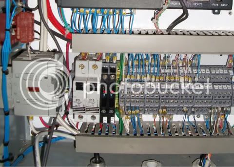
i'm planning on using the dpdt as a "switch". Similar to a SSR, a DPDT needs some sort of signal to close the circuit. In the case of a SSR this is a 12VDC signal from the PID (or some other source). For a DPDT you have a coil which is rated to a certain voltage, when that voltage is applied to the coil, and electromagnetic reaction occurs which closes the circuit. The contactors to which the 2 hot wired are connected close and allow the current to pass through into the element.
My question has to do with the voltage i am applying to the coil. It will be supplied with a 120V hot wire, since my coil requires 120Vac to close. My question is, do i need a neutral wire on the other end of the coil going back to the terminal block?
Maybe - What is the make and model number of the device you are calling a "DPDT"?
It looks from the pic like a contactor or power relay, but I need more information.
How many posts - What are they labeled?
ClaudiusB
Well-Known Member
Stage #1: elements to be controlled manualy through the use of 2 allan bradley selector switches.
What contact blocks are you using for the E-Stop and 30 mm NEMA switches?
Standard A-B contact blocks are rated 10A continuous.
Cheers,
ClaudiusB
sweetsounds: I dont have the dpdt in front of me now (at work) and for the life of me i can't remember the info, i'll post it later when i get home.
ClaudiusB: As for the e-stop, i'm rethinking the way i have that set up, my electricians at work pointed out the same issue to me, so i'm not quite sure how i will change that up. any suggestions?
ClaudiusB: As for the e-stop, i'm rethinking the way i have that set up, my electricians at work pointed out the same issue to me, so i'm not quite sure how i will change that up. any suggestions?
ClaudiusB
Well-Known Member
ClaudiusB: As for the e-stop, i'm rethinking the way i have that set up, my electricians at work pointed out the same issue to me, so i'm not quite sure how i will change that up. any suggestions?
Your electrician could have recommended a master control relay controlled by the E-Stop to supply/cut power
")
Or a simple disconnect rated for your application.
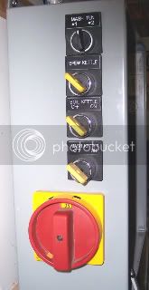
50A disconnect, overkill for my gas fired setup
Cheers,
ClaudiusB


$53.24
1pc Hose Barb/MFL 1.5" Tri Clamp to Ball Lock Post Liquid Gas Homebrew Kegging Fermentation Parts Brewer Hardware SUS304(Liquid Hose Barb)
Guangshui Weilu You Trading Co., Ltd


$20.94
$29.99
The Brew Your Own Big Book of Clone Recipes: Featuring 300 Homebrew Recipes from Your Favorite Breweries
Amazon.com


$39.22 ($39.22 / Count)
Brewer's Best Home Brew Beer Ingredient Kit - 5 Gallon (Mexican Cerveza)
Amazon.com


$27.29 ($13.64 / Count)
$41.99 ($21.00 / Count)
2 Pack 1 Gallon Large Fermentation Jars with 3 Airlocks and 2 SCREW Lids(100% Airtight Heavy Duty Lid w Silicone) - Wide Mouth Glass Jars w Scale Mark - Pickle Jars for Sauerkraut, Sourdough Starter
Qianfenie Direct

![Craft A Brew - Safale BE-256 Yeast - Fermentis - Belgian Ale Dry Yeast - For Belgian & Strong Ales - Ingredients for Home Brewing - Beer Making Supplies - [3 Pack]](https://m.media-amazon.com/images/I/51bcKEwQmWL._SL500_.jpg)


$53.24
1pc Hose Barb/MFL 1.5" Tri Clamp to Ball Lock Post Liquid Gas Homebrew Kegging Fermentation Parts Brewer Hardware SUS304(Liquid MFL)
yunchengshiyanhuqucuichendianzishangwuyouxiangongsi

$10.99 ($31.16 / Ounce)
Hornindal Kveik Yeast for Homebrewing - Mead, Cider, Wine, Beer - 10g Packet - Saccharomyces Cerevisiae - Sold by Shadowhive.com
Shadowhive


$176.97
1pc Commercial Keg Manifold 2" Tri Clamp,Ball Lock Tapping Head,Pressure Gauge/Adjustable PRV for Kegging,Fermentation Control
hanhanbaihuoxiaoshoudian

$719.00
$799.00
EdgeStar KC2000TWIN Full Size Dual Tap Kegerator & Draft Beer Dispenser - Black
Amazon.com


$22.00 ($623.23 / Ounce)
AMZLMPKNTW Ball Lock Sample Faucet 30cm Reinforced Silicone Hose Secondary Fermentation Homebrew Kegging joyful
无为中南商贸有限公司


$7.79 ($7.79 / Count)
Craft A Brew - LalBrew Voss™ - Kveik Ale Yeast - For Craft Lagers - Ingredients for Home Brewing - Beer Making Supplies - (1 Pack)
Craft a Brew


$58.16
HUIZHUGS Brewing Equipment Keg Ball Lock Faucet 30cm Reinforced Silicone Hose Secondary Fermentation Homebrew Kegging Brewing Equipment
xiangshuizhenzhanglingfengshop


i was just perusing another control panel build and i came across this same picture you just posted. I think i might go that route instead of the estop (even though i got the estop free from work). It seems like a simple enough concept....2 hot lines into disconnect, when flipped to OFF whole system has zero power when flipped to ON whole system is energized, right?
Similar threads
- Replies
- 8
- Views
- 581
- Replies
- 20
- Views
- 1K
- Replies
- 11
- Views
- 968

Latest posts
-

-

-

-
 Factors affecting Water Chemistry Calculations (Oh no, not again!)
- Latest: Unicorn_Platypus
-

-

-