Another Brucontrol Build

Homebrew Talk - Beer, Wine, Mead, & Cider Brewing Discussion Forum

Help Support Homebrew Talk - Beer, Wine, Mead, & Cider Brewing Discussion Forum:

This site may earn a commission from merchant affiliate links, including eBay, Amazon, and others.

jEld

Supporting Member
HBT Supporter
Joined
Jan 16, 2012
Messages
62
Reaction score
24
Location
Oxford
First off, this forum has been great to me over the years and everyone has been beyond helpful. After working all summer as an assistant brewer at the new brewery in town (sometimes being a teacher works out for me), I haven't been able to resist the urge to increase my capacity and process. Thanks to the advice here, I am getting ready to begin building 30A 3 vessel rig controlled by Brucontrol. I've already sourced the majority of my components and I am waiting for them all to trickle in. Black Friday was good to me!

As I wait, I have spent some time working on adapting Brundog's schematic to my current goals, which are:

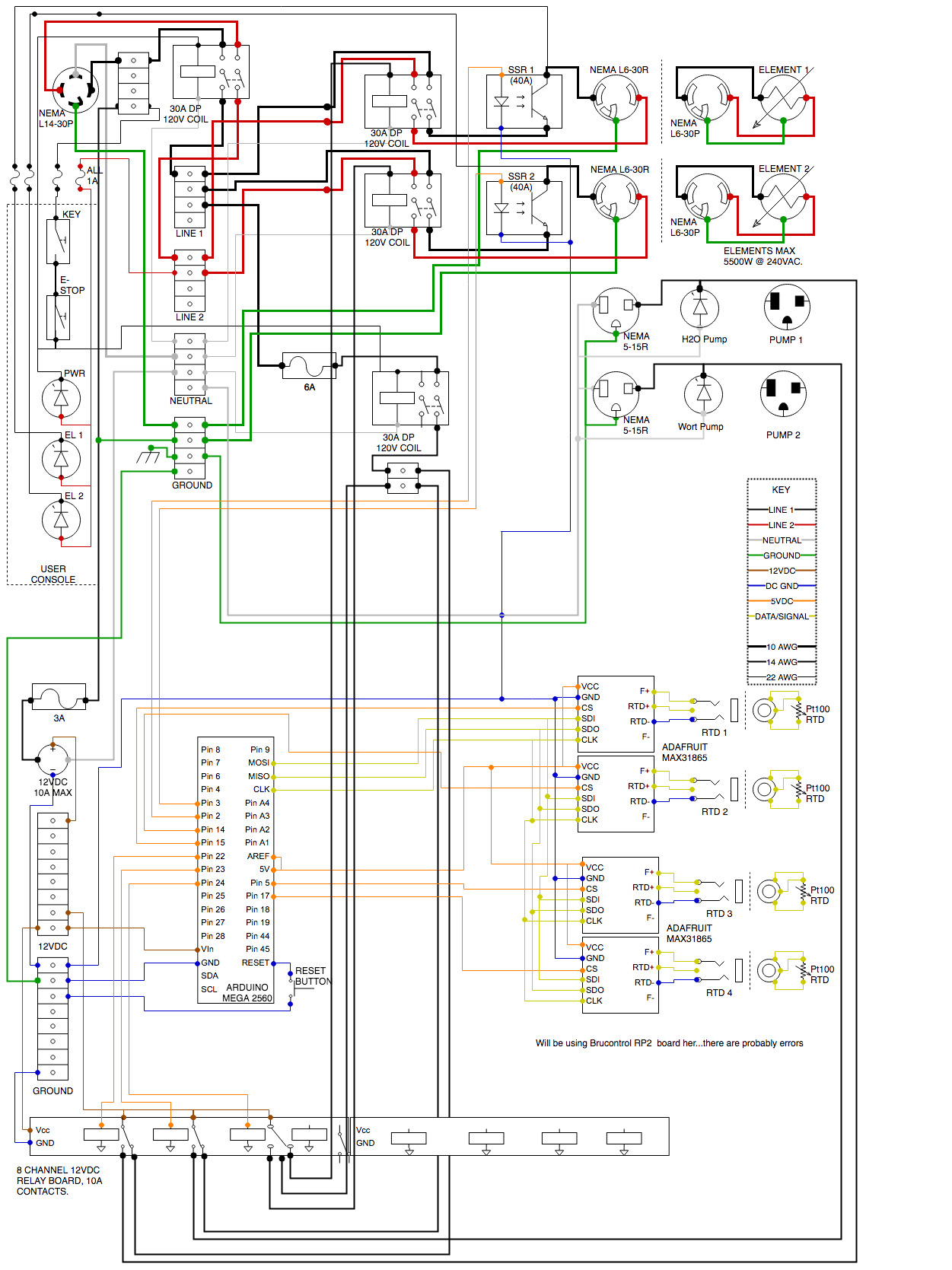
1) Have a system that can be as automated as I would like it eventually, but start out as a basic PID control panel, but on a computer screen.

2) My wiring (should) allow the e-stop to kill the pumps and elements, but allow the 12V supply keep the Brucontrol software up and running.

3) The relay board should prevent both elements from firing at the same time rather than relying on software alone.

I'm including my diagram in the hopes that if I have a major misunderstanding, that other eyes could catch it! Thanks in advance if you do!
 

Attachments

  • Brucontrol Panel-1.pdf
    244.2 KB · Views: 189
  • Brucontrol Panel.jpg
    Brucontrol Panel.jpg
    542 KB · Views: 241
My wiring (should) allow the e-stop to kill the pumps and elements, but allow the 12V supply keep the Brucontrol software up and running.

@jEld , I think that makes two of us building a BruControl rig right now. We have to come up with a secret handshake and a rules committee, I guess.

@BrunDog and I have gone out to the woodpile a couple of times over this, but if I need to hit an E-stop, I want the panel, and as much else as I can kill, as dead as a fencepost. I know he wants to keep a heartbeat on his MEGA, but if it's an emergency, like hot wort spraying on a kid, I don't much care about the batch any more. I just want a big red button to smack that I know will help stop the emergency.

Your situation may be different, so proceed as you like.

I'm in a similar situation as you, in that I am going to run a panel designed for 50A service off of a 30A dryer outlet until I can assemble the necessary sofa change to have someone drop a 100A subpanel in my garage, part of which will be dedicated to the brewery. I need to see about a temporary interlock circuit that will prevent firing both elements at the same time. Having read several threads about guys that dry-fired their elements, it might be nice to sort out the sensors and circuits needed for an immersed element interlock, too. Gonna scratch my head on that one, as well.
 
Sounds good @GParkins... for me, I could see myself hitting the e-stop because I stupidly forgot to hook up a hose or something, and not want to have to reach for a mouse/touchscreen...I considered not even using the e-stop altogether but wanted it for peace of mind.
 
Sounds good @GParkins... for me, I could see myself hitting the e-stop because I stupidly forgot to hook up a hose or something, and not want to have to reach for a mouse/touchscreen...I considered not even using the e-stop altogether but wanted it for peace of mind.

Maybe we should add an orange button and call it a D-stop (******* stop)?
 
Trying to follow your modified diagram and noticed you have 2 legs off your E-Stop. One leg goes to the 110V of the main power contactor the other to the 110V contactor which controls the relays for the 2-240V and 110V pump circuits. The way I see it when the E-Stop is engaged you are killing the main power contactor and everything past it? In other words the secondary leg is redundant.

On a side note I'm also in the midst of building my brew/fermentation panel using BruControl and an extension panel to house the E-stop, switches,LED's etc.. As far as the possibility of dry firing or accidentally switching 2 elements at the same time I'm adding an additional layer of protection I'm using a three position switch after the relay. The reason being for me relays can fail and stay stuck on when not intended, however I'm extra cautious about things like this so physically moving a switch during the brew process is no big deal to me.
 
Last edited:
Good catch on that...guess I don’t need to worry about that extra contactor...I made a few changes and didn’t look back at that. Thanks. Hadn’t really considered the possibility of a dry fire of the element from the relay. Might have to consider a selector switch as well...
 
I am working from the road on an iPad. I will take a better look when I get home. First glance should me that you have the relay board COM terminals tied to 12V but the NO and NC contacts to 120V. This would not be correct, unless your goal is to smoke the DC supply.
 
Duly noted...and corrected. I'll wait for any other feedback before uploading the current revision! I've removed the unnecessary pump contactor and changed the wiring of the relay board in the schematic to reflect the 120V switching.
 
I think your other edits are electrically sound. A few comments of my opinions, if that’s worth anything: As you know, you will not be able to turn off the controller without unplugging the control panel. The 30A dual pole contactor in the middle of the page is superfluous as it serves the same function as the main 63A relay - you can just eliminate it and go straight from the 6A fuse to the small 4 pole terminal block.

In addition, the key switch and E-Stop serve the same function. I realize they act differently and the key may lock out users, but I suggest you contemplate how you will be using your system before committing the design. You may not need both - the E-Stop should suffice alone.

We also added LEDs for the element powers as they will pulse very quickly when controlled by PID - often too fast to register on the computer screen. However, you might hold on the pump LEDs as these will require additional holes and lights that will reflect the same information in the screen. Should you want to use other channels on the relay board, would it mean more LEDs to cut etc.
 

Latest posts

Back
Top