An issue testing RIMS controller

Homebrew Talk - Beer, Wine, Mead, & Cider Brewing Discussion Forum

Help Support Homebrew Talk - Beer, Wine, Mead, & Cider Brewing Discussion Forum:

This site may earn a commission from merchant affiliate links, including eBay, Amazon, and others.

burdbrew

Well-Known Member
Joined
May 9, 2009
Messages
175
Reaction score
56
Location
Vermont
Hello all,

I have wired up a RIMS toolbox (inspired from countless threads on this forum). When I plug a lamp in and put the thermocouple in cold enough water to turn the element on, my outlet tester tells me that I am wired correctly, however when I plug in a lamp, the lamp won't turn on (I tried the lamp directly in the wall and it works fine). Am I missing something simple?
 
There are so many small things that could look right but aren't. It could be a tiny strand of a wire shorting out. You could have a faulty part. You just need to go over it with a find tooth comb.
 
Don't forget that you want to make sure you are switching only one side of the power. For instance, the neutral should go from your power source to your outlet. The hot should go from your power source to one side of the SSR, then from the other side of the SSR to the outlet.

The other posts on the SSR are for the control circuit from your PID.
 
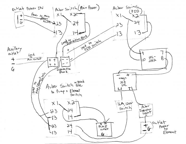
My apologies in advance for my drawing. Most diagrams on this forum are outstanding; mine, maybe not so much.

I have main power going in to a switch and then to a distribution block. I have three loads from that block. One to an outlet, one to a switch for the pump and element (set up so the element can't run without the pump being engaged) and one for the PID. All grounds are attached together.

The switch from the pump provides a load to the switch for the element. The power runs from that switch, to the SSR, through an indicator light and finally to power out.

Everything appears to work. When I put a receptacle tester in the element outlet, it operates as it should. When I plug a lamp in, it will not light up.

Burd Rims diagram.jpg
 
It looks to me like you have the output of your SSR going through the indicator light to the element outlet. This may allow enough current flow to illuminate the outlet tester, but nothing more. You need a direct wire from SSR out to the element outlet and the indicator light in parallel or across the outlet to show when it's energized.

I'm not familiar with the Auber switch terminal numbers, but it looks like you're switching both sides of the line? Is everything 240V? If you're using 120v, it's probably best not to switch the neutral side.
 
I have wired the switch wrong. Thank you.

Points taken on running the indicator in line.

Edit: I believe I need to switch neutral to make the lights work.
 
Back
Top