240V heating element + GFCI wiring sanity check...

Homebrew Talk - Beer, Wine, Mead, & Cider Brewing Discussion Forum

Help Support Homebrew Talk - Beer, Wine, Mead, & Cider Brewing Discussion Forum:

This site may earn a commission from merchant affiliate links, including eBay, Amazon, and others.

carnageasada

Active Member
Joined
Jan 11, 2017
Messages
25
Reaction score
1
Hey all,
Working a unitank to also serve as a BK and have chosen the following element (240V, 4500W):

DERNORD 2 Inch Tri-Clamp 240V Water Heating Element Immersion U Type Electrical Brewing Boiler Heater

So running from a standard single phase 240V dryer plug to a L6-30:
1669858069453.png


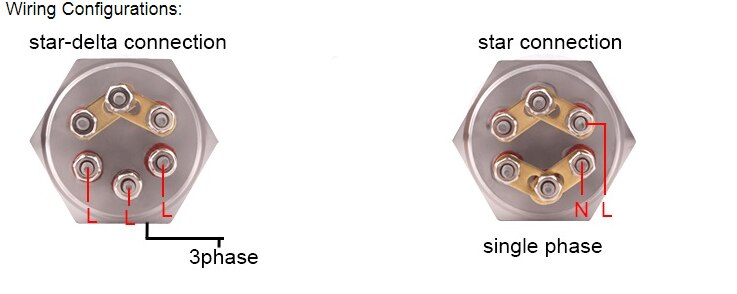
Element wiring diagram is as follows:
1669857944865.png

So it's saying I connect the resistive element in series using a (hot) line conductor and the (green) conductor. What does one do with the other (hot) line in this configuration?

Thanks in advance for any insight!
b
 
NO.

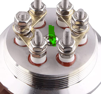
The single phase diagram is assuming a 240v between Hot and Neutral but if you're in the U.S, we have a split phase system. You connect those two poles to the connections that are NOT green. The green wire is supposed to be bonded to this center screw. Just be very careful that the ground can't touch the hot connectors.

1669862414761.png
 
There's another diagram on the Amazon page showing the "earthing" connection as the center screw, not among the 2 sets of link threes. So Hot (black) to one leg of three pins, and Hot (red) to the second set of three pins. Neutral to no connection, and Ground (green) to the "earthing" screw to and also the pot itself.

Edit: See Bobby's post, arrived before I could enter all this using my phone.
 
Beautiful, thanks! I saw the threads in that center hole after I posted so your post makes total sense, Bobby. I'm going to use potting material on this after assembled to keep it from falling apart, so that will keep the ground isolated.
 
A follow up question would be how to get a GFCI in-line with this element. Is it correct that currently, this bi-phase configuration will not work as a single phase GFCI like this, depends on a single hot line referenced to a neutral line? But, I have a neutral to use at my source, making the 240V from the wall, white - neutral; black - line; and green - ground. With this and the wiring shown on the right in my original post for the heating element, I will effectively have single phase AND I can introduce a beefy single phase GFCI for protection. Everything seems to check out, but I'd still like to ask:

Informed question(?) - Can I assume the heating element will still work as expected, just as single phase?

Way less informed question - a single phase GFCI wouldn't work with 2 hot lines, right? It would just trip and not be able to do its job since V-V=0, nothing for it to reference?
 
Last edited:
A follow up question would be how to get a GFCI in-line with this element. Is it correct that currently, this bi-phase configuration will not work as a single phase GFCI like this, depends on a single hot line referenced to a neutral line? But, I have a neutral to use at my source, making the 240V from the wall, white - neutral; black - line; and green - ground. With this and the wiring shown on the right in my original post for the heating element, I will effectively have single phase AND I can introduce a beefy single phase GFCI for protection. Everything seems to check out, but I'd still like to ask:

Informed question(?) - Can I assume the heating element will still work as expected, just as single phase?

Way less informed question - a single phase GFCI wouldn't work with 2 hot lines, right? It would just trip and not be able to do its job since V-V=0, nothing for it to reference?
That linked GFCI will work fine. It contains the two hot lines and ground, but does not have a neutral (so you can't get 120V from it, only 240V.) If your dryer outlet has only three slots, then the connections are hot 1, hot 2, and ground, but no neutral. If you tried to cheat and get 120V between one of the hots and ground (like older dryers do) then you will trip the GFCI.

A GFCI does not measure voltage at all. It detects a differential in outgoing vs. return current, and trips if a differential is detected. In the absence of a fault, all current flows in conductors intended to carry current, so the outgoing and return currents are equal (0 differential.) If some of the current gets diverted (say into your body) then the currents no longer balance, and the GFCI trips. It only takes ~5mA of current imbalance to trip a GFCI.

In a 120V application, current flows in the hot and neutral lines, and the GFCI monitors for balance in those currents. In a US style 240V application, the GFCI monitors the two hots for balance. In a mixed 120V/240V application, the GFCI monitors both hots and the neutral.

120V/240V applications are not intuitive to those who don't fully understand how currents flow in loops. But say you have an application that has a heating element that draws 23A@240V and 120V pump and control circuitry that draw 2A@120V, and get power from hot 1. Hot 1 will have 25A running thru it, hot 2 will have 23 A running thru it, and neutral will have 2 A running thru it. The currents in hot 2 and neutral are flowing in the opposite direction from hot 1, so the differential current is still 0.

Brew on :mug:
 
Last edited:
Doug, solid copy, that's good news! I just measured at the wall and answered my question solid that Bobby pointed out earlier - this is bi-phase and if I use only a single leg, my only option is 120VAC, which is a fail...

Bobby, I'm working in a "local" GFCI strictly for this load, but not at the panel if I can manage. Just doubling down from my fuse box cause, well, why not...?
 
Last edited:
Doug, to be clear, you're saying, I CAN use that GFCI inline as - white hot; black hot; green ground? No changes...? The instructions call it out as a single phase speaking to one conductor as neutral. Note that this is fed by a 4 wire outlet at the wall which does have a neutral I could use. Looking at the printed instructions:


View attachment 807109

Literally just calls out line 1 black to primary line 1 and line 2 white to primary line 2. But, the pic on the left has black = hot and white = neutral?

Bobby, I'm working in a "local" GFCI strictly for this load, but not at the panel if I can manage. Just doubling down from my fuse box cause, well, why not...?
Yes.

The electricity doesn't care what color the wire insulation is. The colors vs. wire use are a convention (set out in the electrical code) that makes sure everyone knows what's going on.

In a 240V feed with 4 wires, the convention is that hot 1 is black, hot 2 is red, neutral is white, and ground is green. In a 240V feed with only 3 wires, there is no red wire, just black, white, and green. So the convention says use the white wire for hot 2, and there is no neutral. Three wire 240V feeds are used because three wire cable is cheaper than four wire cable.

The GFCI you are looking at is a three wire only device. When used for 120V, the white wire is neutral, and when used for 240V the white wire is hot 2. If you read the directions for wiring 240V, that's what it says. The picture labeling is only correct for 120V use.

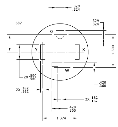
Your four wire outlet should look like this:

1670188418026.png


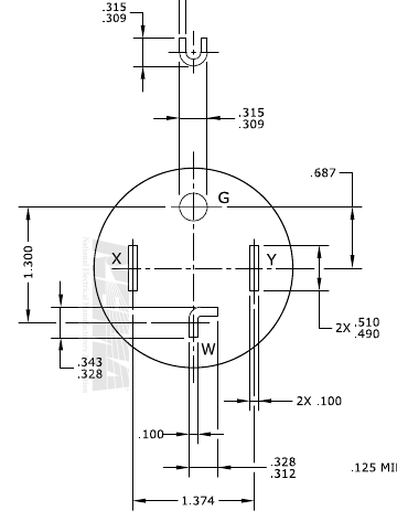
And the plug should look like this:

1670188562115.png

The "bent" blade/slot labeled "W" is the neutral connection. In your application, this blade will not be connected in the plug. The white and black wires will be connected to the straight blades labeled "X" and "Y" - it doesn't matter which is which. So, you will not be using neutral, even tho it is there in the outlet. Your element does not have a neutral connection.

What Bobby is suggesting is to make your own GFCI extension cord by using a Spa panel, which is separate from your main panel. It would cost about 1/2 as much as the GFCI cord you are looking at, but will be bulkier. One advantage of the Spa panel is that it is designed for four wire input, so it can provide both 240V and 120V output (your choice provides one or the other, but not both.)

Given your level of confusion about how things should be wired, I highly recommend that you find someone with expertise locally, who can help you do the wiring. This stuff can kill you, or burn your house down, if you get it wrong (not always, but it's a real risk.)

Brew on :mug:
 
If you can't change out the breaker for a GFCI enabled one (~$120) because you're worried about nuisance tripping with the dryer, a spa panel might be the way to go.
If the four wire dryer cord is properly connected inside the dryer, then you should not trip a GFCI in the main panel. If the dryer cord isn't properly connected, or the dryer cord is only three wire, then it will always trip a GFCI in the main panel, if there are any 120V components in the dryer.

Brew on :mug:

I've heard at least a dozen reports of a 4-wire dryer circuits tripping a newly installed GFCI breaker. If it were just one or two, I'd blame a faulty appliance or user error, but it's more than that. I don't have any ideas why it would happen but it looks like there are a lot of discussions on electrical forums about inductive loads nuisance tripping GFCIs.
 
Last edited:
I've heard at least a dozen reports of a 4-wire dryer circuits tripping a newly installed GFCI breaker. If it were just one or two, I'd blame a faulty appliance or user error, but it's more than that. I don't have any ideas why it would happen but it looks like there are a lot of discussions on electrical forums about inductive loads nuisance tripping GFCIs.
It might be improper installation of the dryer. Many dryers are capable of being installed for either 3-wire or 4-wire operation. There is an internal jumper between ground and neutral that stays connected for a 3-wire installation, but must be removed for a proper 4-wire installation. If you neglect to remove the jumper in a 4-wire installation, you will trip the GFCI, due to some current bypassing the neutral return, since it flows in the ground wire. Sump pumps are regularly run on GFCI protected circuits, and I can't imagine the motor in a dryer being more of a problem than a pump motor.

Brew on :mug:
 
Well, in my case, GFCI installed and no trip, tested fine too. Think I'm good. Thanks for all the advice and hope this thread can help others in a similar situation, even if they think they just need to defer to a local pro opinion.
 
When initially wiring a GFCI circuit in my brew room, the schematic below helped me visualize how the 240-volt wiring needed to be done.

View attachment 807124

The same 4-wire GFCI outlet I posted earlier also serves double duty when plugging in my 3-wire brew room heater. Of course, the outlet only powers either the kettle heating element or the space heater at a time.


240-3-heater.jpg
 
Yes.

The electricity doesn't care what color the wire insulation is. The colors vs. wire use are a convention (set out in the electrical code) that makes sure everyone knows what's going on.

In a 240V feed with 4 wires, the convention is that hot 1 is black, hot 2 is red, neutral is white, and ground is green. In a 240V feed with only 3 wires, there is no red wire, just black, white, and green. So the convention says use the white wire for hot 2, and there is no neutral. Three wire 240V feeds are used because three wire cable is cheaper than four wire cable.

The GFCI you are looking at is a three wire only device. When used for 120V, the white wire is neutral, and when used for 240V the white wire is hot 2. If you read the directions for wiring 240V, that's what it says. The picture labeling is only correct for 120V use.

Your four wire outlet should look like this:

View attachment 807118

And the plug should look like this:

View attachment 807119
The "bent" blade/slot labeled "W" is the neutral connection. In your application, this blade will not be connected in the plug. The white and black wires will be connected to the straight blades labeled "X" and "Y" - it doesn't matter which is which. So, you will not be using neutral, even tho it is there in the outlet. Your element does not have a neutral connection.

What Bobby is suggesting is to make your own GFCI extension cord by using a Spa panel, which is separate from your main panel. It would cost about 1/2 as much as the GFCI cord you are looking at, but will be bulkier. One advantage of the Spa panel is that it is designed for four wire input, so it can provide both 240V and 120V output (your choice provides one or the other, but not both.)

Given your level of confusion about how things should be wired, I highly recommend that you find someone with expertise locally, who can help you do the wiring. This stuff can kill you, or burn your house down, if you get it wrong (not always, but it's a real risk.)

Brew on :mug:
One critical item to add: the GFCI device MUST be 2-pole for USA 240V single phase circuits. That linked device is fine. A 1 pole GFCI device won't open both hots, leaving the load energized. (Also, all of your switches and relays should be 2-pole.)
 
One critical item to add: the GFCI device MUST be 2-pole for USA 240V single phase circuits. That linked device is fine. A 1 pole GFCI device won't open both hots, leaving the load energized. (Also, all of your switches and relays should be 2-pole.)
Absolutely correct. Every hot needs a pole in the GFCI in order for complete protection. The GFCI's linked by the OP do have 2 poles. A screen grab from the spec sheet:

1670378895656.png


Brew on :mug:
 
Back
Top