• Please visit and share your knowledge at our sister communities:
  • If you have not, please join our official Homebrewing Facebook Group!

    Homebrewing Facebook Group

2250watt element tripping 20 amp breaker

Homebrew Talk

Help Support Homebrew Talk:

This site may earn a commission from merchant affiliate links, including eBay, Amazon, and others.
What are you basing this on? You are suggesting that the NEC ampacities are not safe enough. You can certainly do what you suggest, without any safety concerns, but according to best available guidance, it is totally unnecessary. Heavier wire is more costly, and harder to work with.

Brew on :mug:
what am I basing this on???? Dude ,you need to talk to an electrician. Yes heavier wire is more expensive and yes can be hard to work with . But think about safety and codes . I realize the local codes dont mention brewing systems but there is a "common sense approach" to building an electrical system. Basing your build on cost and ease vs the right way and safety is not a good choice . Theres a reason there isn't 14/3 running the 220 to your house service panel. If it was about easy and cheap there would be. Same with why aluminum wire was outlawed years ago. Its a thing called house fires.
How about GFCI's - I mean theyre expensive and do we really need them just because we're near water??? Theres a reason they were invented. The warning labels on nearly everything are put there because somebody died from doing something stupid.
Go sit through an OSHA 10 course sometime, it will open your eyes.
 
Last edited:
I didnt read the entire thread but I wanted to share that the 80% rule does not apply here unless your boiling your wort at 100% power for more than 3 hrs straight. The definition of continuous load in this instance is 100% load for more than 3 hrs.

I would venture to guess the automotive fuse holders were the weak point.. also your breaker or breaker connection may be faulty.

I run my whole setup off a 30a circuit at home including multiple elements and the pumps and panel. ive pulled 28amps on my meter for periods of time and never once in over 5 years tripped the breaker of popped a fuse (I use radioshack fuser holders with 25a fuses)
 
Last edited:
I wouldnt push any more than 15 amps through 14 ga wire. 10ga for 20 amps and 6ga for 30amps (220v)
This is not completley correct... sorry I work with this stuff everyday. 10awg is rated for 30a 6awg is what the 60a service for my hot tub runs off of. 8awg is typically 40a.

It does depend on the type of cable, installation and length in some cases... For example for my 5500w elements at home I use 12awg sj cable which stated right on it is rated for 300v-25a because of the type of use. some types are only rated for 20a as in most instances 12g is rated for 20a...
heres a nice chart that touches on what I mean.

https://www.cerrowire.com/products/resources/tables-calculators/ampacity-charts/

btw my home brewery runs off a 10awg romax fed 30a circuit.
 
Last edited:
what am I basing this on???? Dude ,you need to talk to an electrician. Yes heavier wire is more expensive and yes can be hard to work with . But think about safety and codes . I realize the local codes dont mention brewing systems but there is a "common sense approach" to building an electrical system. Basing your build on cost and ease vs the right way and safety is not a good choice . Theres a reason there isn't 14/3 running the 220 to your house service panel. If it was about easy and cheap there would be. Same with why aluminum wire was outlawed years ago. Its a thing called house fires.
How about GFCI's - I mean theyre expensive and do we really need them just because we're near water??? Theres a reason they were invented. The warning labels on nearly everything are put there because somebody died from doing something stupid.
Go sit through an OSHA 10 course sometime, it will open your eyes.
again your suggestions were not code, they were overkill for code. contractors dont use 6awg for 30a circuits they install in construction. They use 10awg because thats what its rated for.
The reason 14/3 wire isnt used for 220v circuits in a house is simlpy that they are generally all 20a or higher... I dont believe I saw anywhere in this thread where it was suggested to run a 20a 240v circuit with 14 romex wire. That said I believe it may meet code if its the correct type of installation in an enclosed control panel where for example a piece of wire is running from a din breaker to an outlet in the panel. the chart linked above reinforces that. This is also why things like cartridge heaters often have smaller gauge wire coming out of them but with a high temp insulation and still meet code.

and aluminum wire is not "outlawed" its no longer allowed to be installed for certain applications but its still used and made... The main power feed in my house is aluminum clad wire. Installed in the 70s and never been an issue..
 
Last edited:
I didnt read the entire thread but I wanted to share that the 80% rule does not apply here unless your boiling your wort at 100% power for more than 3 hrs straight. The definition of continuous load in this instance is 100% load for more than 3 hrs.

I would venture to guess the automotive fuse holders were the weak point.. also your breaker or breaker connection may be faulty.

I run my whole setup off a 30a circuit at home including multiple elements and the pumps and panel. ive pulled 28amps on my meter for periods of time and never once in over 5 years tripped the breaker of popped a fuse (I use radioshack fuser holders with 25a fuses)

Thank you Auggiedoggy. Doug had stated that previously as well. I’m very glad to hear from the both of you that running above the 80% circuit capacity is ok. As you could tell, that was my major concern.
Since that first test I have tested the system with water 2 other times and then performed a first brew on it Wednesday and encountered NO problems whatsoever with the breaker tripping and the wiring stayed cool to the touch. The system from a build standpoint operated wonderfully. I did have erratic pv temps halfway thru the mash that I believe to be caused by my cheesy rtd wire, which I plan to replace with another temp probe as well.
Thanks all again.
 
I have had rtd spikes and have heard of them happening from ground loops when the rtd wire ground shielding is grounded at both ends at both the kettle and control panel. the issue is there is already anpother ground path created with the ground from the heating element power cord and this can sometimes create a ground loop that some pids and ardino/pi setups arent filtered correctly against. just something to look for .. inmy case the element actually firing would sometimes cause the temp probe reading to go whacky.
 
Jbrew,

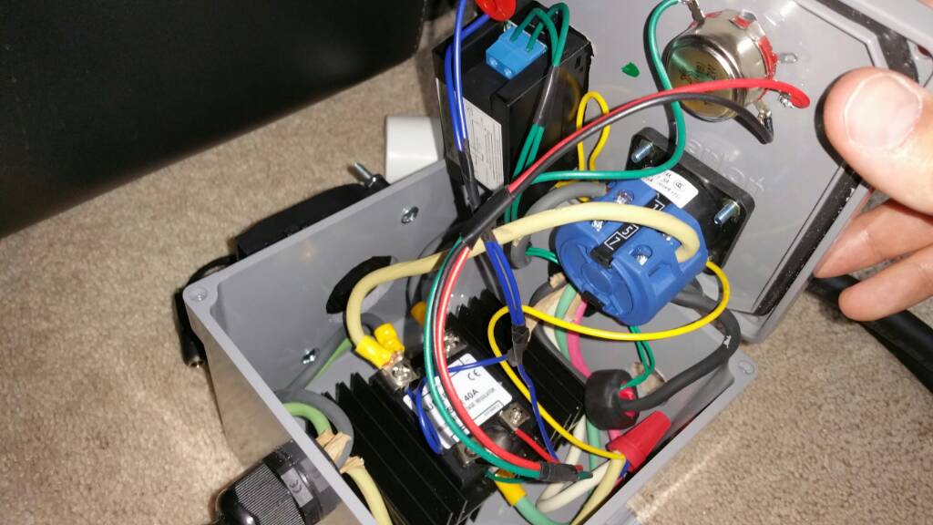
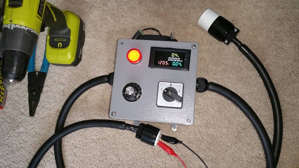
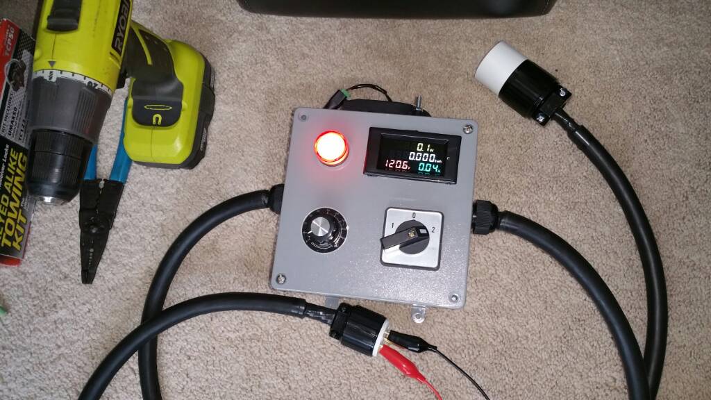
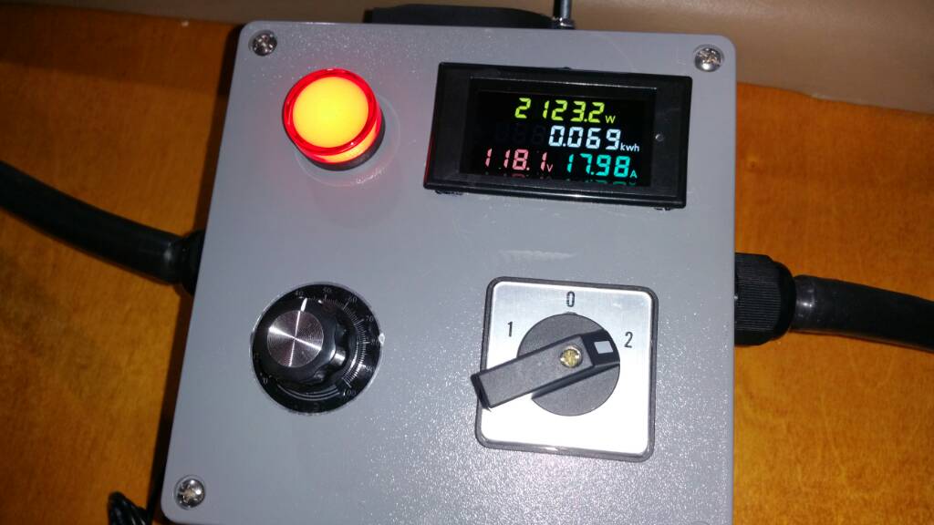
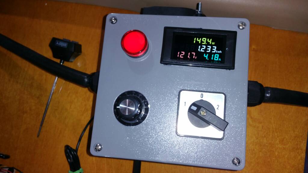
As promised here is my setup just finished building, same element you have, 120V. I have a 20A 12AWG circuit with a 20A GFCI installed.

In retrospect I should have gone with an 8x8x4 box instead of the 6x6x4. I have a 33CFM fan that draws hot air out the top, and brings incoming cooler air via two holes on the side. May upgrade box size later. I couldnt fit the 12VDC psu for the fan inside, so its outside for now. Air flow seems adequate to me.

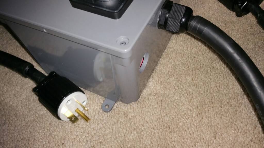
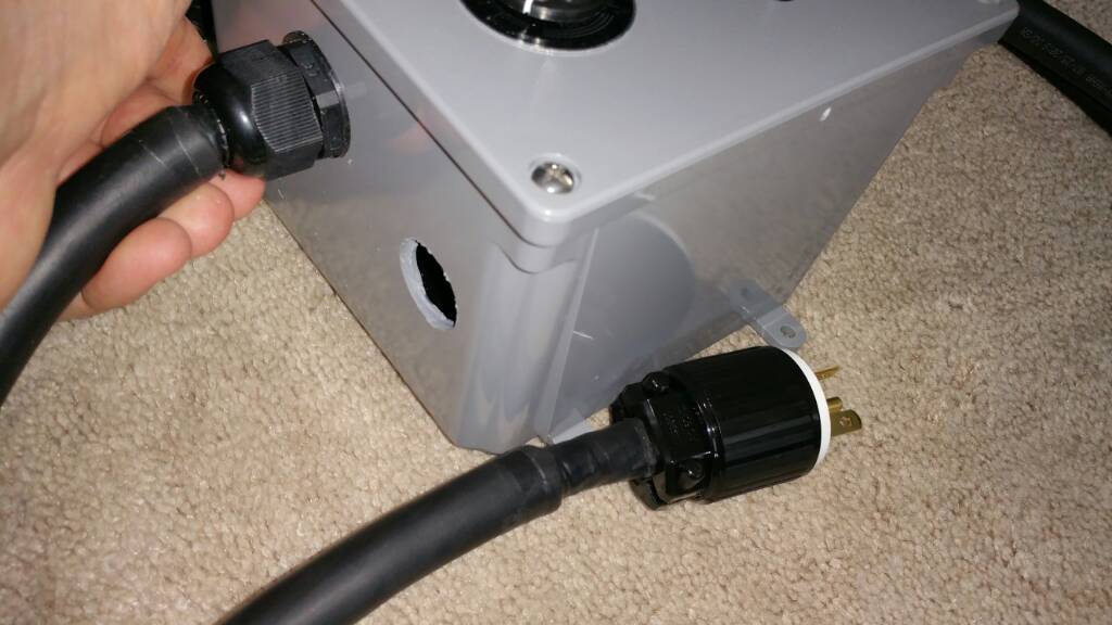
FYI I built this with 10AWG SJ wire. The input cord is 10/4 as eventually I will upgrade to 240V down the road. The element cord is 10/3.

3 position switch rated 25A. Meter is always powered. Testing will reveal how accurate it is. 0 is off, 1 is through the SSVR, and 2 bypasses the SSVR directly to the element so as not to waste energy/heat. You can see the difference in the indicator light brightness. Minor note, i accidently bought a NEMA 6-20P, when I really needed a 5-20P to fit my GFCI. Going to Depot now to swap out.

Sorry to hijack, ill open my own thread for more detail, but figured since this thread has had plenty of eyes on it the post was relevant.
20190405_115412.jpg
20190405_115323.jpg
20190405_115318.jpg
20190405_115314.jpg
20190405_114747.jpg
20190405_114801.jpg
20190405_114809.jpg
 
I have had rtd spikes and have heard of them happening from ground loops when the rtd wire ground shielding is grounded at both ends at both the kettle and control panel. the issue is there is already anpother ground path created with the ground from the heating element power cord and this can sometimes create a ground loop that some pids and ardino/pi setups arent filtered correctly against. just something to look for .. inmy case the element actually firing would sometimes cause the temp probe reading to go whacky.

Interesting. Thank you for the heads up, however, I don’t think I’ll have that problem. My panel is actually a plastic box.
The wire is metal braided, and came with only a disconnect on one side. The other side I removed the fork terminals and soldered a quick disconnect on so that it can be removed from the panel and the kettle. I’ve had it apart twice now to confirm my solder contacts. The wire inside the braiding seems to be covered with a mesh nylon or maybe even fiberglass, because it was pretty itchy when I got it on my skin after trimming it back.
When I move the wire around or bend it a bit while in use it, also causes the readings to jump or at times the PID to display EEEE suggesting it loses contact. I’m going to assume that’s not normal is it?
 
what am I basing this on???? Dude ,you need to talk to an electrician. Yes heavier wire is more expensive and yes can be hard to work with . But think about safety and codes . I realize the local codes dont mention brewing systems but there is a "common sense approach" to building an electrical system. Basing your build on cost and ease vs the right way and safety is not a good choice . Theres a reason there isn't 14/3 running the 220 to your house service panel. If it was about easy and cheap there would be. Same with why aluminum wire was outlawed years ago. Its a thing called house fires.
How about GFCI's - I mean theyre expensive and do we really need them just because we're near water??? Theres a reason they were invented. The warning labels on nearly everything are put there because somebody died from doing something stupid.
Go sit through an OSHA 10 course sometime, it will open your eyes.
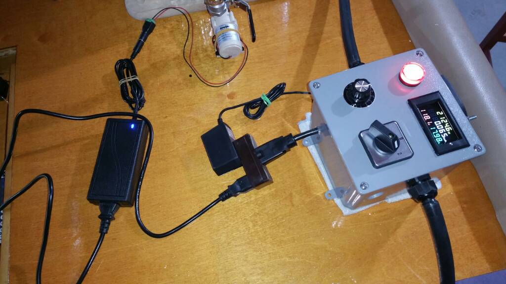
As @augiedoggy has already noted, your post was called out for suggesting people needed to use wire larger than required by code. I thought I was clear enough about that in my previous post, where I said: "You are suggesting that the NEC ampacities are not safe enough." For those who might not know, NEC is the "National Electrical Code" that specifies all kinds of electrical requirements based primarily on what is safe. The "NEC ampacities" are tables that show what wire gauge (AWG) is required for different max currents under different conditions. Here is one such table:

wire-size-table-CU.png


I am very safety oriented and would never suggest anyone implement anything that violates NEC, or that I think has any safety exposures.

Brew on :mug:
 
Beer baron cool build. So your not using a PID or any other type of controller? your just using a manual pwm to the ssr?
I was going to use that volt/watt/ammeter but I decided on a smaller one that lit up red on top and green on the bottom to match the PID. That box looks a little tight but seems to fit ok. I went with an 8x6x4 box with a flip top lid.
 
No PID. Didn't want to put that much automation in at this time. Goal was to ditch propane and go to electric cheaply and effectively as possible. This a voltage regulator, and changing the resistance to the triac inside uses a method called phase angle modulation to vary the power output. Electrically its more noisy than a PID, but being this is on a dedicated circuit with nothing else im not worried about interference of other devices.

Yeah will likely get a bigger box down the road, for now it will work okay. This box I have now was $12 bucks so not a big loss. Will give it a try later today or this weekend and see how everything goes.
 
Last edited:
As @augiedoggy has already noted, your post was called out for suggesting people needed to use wire larger than required by code. I thought I was clear enough about that in my previous post, where I said: "You are suggesting that the NEC ampacities are not safe enough." For those who might not know, NEC is the "National Electrical Code" that specifies all kinds of electrical requirements based primarily on what is safe. The "NEC ampacities" are tables that show what wire gauge (AWG) is required for different max currents under different conditions. Here is one such table:
wire-size-table-CU.png


I am very safety oriented and would never suggest anyone implement anything that violates NEC, or that I think has any safety exposures.

Brew on :mug:

its always kind of irked me when cable manufacturers publish ampacity charts on their websites, at least those that don't provide any additional disclaimer notes. an allowable ampacity chart is only valid for a specific set of installation and use characteristics, which many times the lay person may not understand. ambient temperature variations, termination temperature ratings, conductor counts in a raceway, circuit length, exposure to sunlight, etc. can all impact the allowable ampacity. it can often be fairly complicated to apply all the rules, even for technical people that work with it regularly and a simple table on a manufacturer's website can be misleading.

on the topic of going beyond code, it can come back to bite you, bigger isn't always necessarily better. for example, increasing current-carrying conductor size beyond what code requires also must include a corresponding increase in the ground conductor size, for safe and proper operation of overcurrent protection devices. some equipment terminations may not be rated for the larger conductor either.
 
Interesting. Thank you for the heads up, however, I don’t think I’ll have that problem. My panel is actually a plastic box.
The wire is metal braided, and came with only a disconnect on one side. The other side I removed the fork terminals and soldered a quick disconnect on so that it can be removed from the panel and the kettle. I’ve had it apart twice now to confirm my solder contacts. The wire inside the braiding seems to be covered with a mesh nylon or maybe even fiberglass, because it was pretty itchy when I got it on my skin after trimming it back.
When I move the wire around or bend it a bit while in use it, also causes the readings to jump or at times the PID to display EEEE suggesting it loses contact. I’m going to assume that’s not normal is it?
sounds like you have a broken wire which sadly is common with many of the rtd wires..especially the stainless braided wire.
 
sounds like you have a broken wire which sadly is common with many of the rtd wires..especially the stainless braided wire.
Yea that’s what I was figuring. Like I said, it appears to be a pretty cheesy unit. I bought the RTD w/wire, with a 40a omron ssr and an ‘n2006p’ PID as a package deal for what I think was a decent price shipped from another member on here. For now, no complaints on the ssr or the PID. The PID seems to be a knock off of the sly2352. It doesn’t allow me to make nearly as many adjustments in the settings, but it works for now. I’ll change it out for an auber unit when it gives me reason to think otherwise.
 
its always kind of irked me when cable manufacturers publish ampacity charts on their websites, at least those that don't provide any additional disclaimer notes. an allowable ampacity chart is only valid for a specific set of installation and use characteristics, which many times the lay person may not understand. ambient temperature variations, termination temperature ratings, conductor counts in a raceway, circuit length, exposure to sunlight, etc. can all impact the allowable ampacity. it can often be fairly complicated to apply all the rules, even for technical people that work with it regularly and a simple table on a manufacturer's website can be misleading.

...
Yes, wire ampacities (and the code in general) can get pretty complicated. However, almost all DIY homebrew systems stay out of the realm that triggers amapacity derating. It would be very unusual for a homebrew system to have more than 2 phase conductors, wire run lengths that result in significant voltage drop, or ambient temps high enough to worry about. If people are extending service to another building, or putting in a subpanel, etc. they should definitely consult a licensed electrician, and get the work inspected to make sure it meets code.

Brew on :mug:
 
Yea that’s what I was figuring. Like I said, it appears to be a pretty cheesy unit. I bought the RTD w/wire, with a 40a omron ssr and an ‘n2006p’ PID as a package deal for what I think was a decent price shipped from another member on here. For now, no complaints on the ssr or the PID. The PID seems to be a knock off of the sly2352. It doesn’t allow me to make nearly as many adjustments in the settings, but it works for now. I’ll change it out for an auber unit when it gives me reason to think otherwise.
the stainless braided line rtds are all from the same manufacturer and while the rtds are fine the wire in the cable is finer than human hair... doesnt matter where you buy it or how much you pay, auber sells the same crappy wire as an upgrade believe it or not. Remember these are $8 shipped for the whole assy on ebay.

I switched all my probe cables both at home and at the brewery to the telfon cables... much much better, no issues since.

I know of the auber knock off pids... The real auber units are also chinese made so it was inevitable but Ive heard they work just as well myself.

Hmmm, I was thinking of purchasing an auber cable and RTD as a replacement. Not so sure now. I was looking at the cables that’s made over at theelectricbrewery.com. They do look nice, but pricey though, and comes only with an Xlr end on it. Better I guess, but I have a regular quick disconnect on each side, the temp probe and on the panel. I would assume that there decent quality but just not sure I’m ready to spend that much more yet.
 
As @augiedoggy has already noted, your post was called out for suggesting people needed to use wire larger than required by code. I thought I was clear enough about that in my previous post, where I said: "You are suggesting that the NEC ampacities are not safe enough." For those who might not know, NEC is the "National Electrical Code" that specifies all kinds of electrical requirements based primarily on what is safe. The "NEC ampacities" are tables that show what wire gauge (AWG) is required for different max currents under different conditions. Here is one such table:

wire-size-table-CU.png


I am very safety oriented and would never suggest anyone implement anything that violates NEC, or that I think has any safety exposures.

Brew on :mug:
the reason for my comment was that he was planning to push 30 amps through 14 ga wire...
 
the reason for my comment was that he was planning to push 30 amps through 14 ga wire...
Maybe this is where the misunderstanding is but thats not at all what he said, at least from what I can find going back..... You dont "push" amps through wire he asked if what he read about having to use fuses to step down and protect smaller wire and amperage circuits powered off a larger main breaker in a control panel to power smaller things in his panel like pumps or pids and to protect that wire (which only has an amp or 2 of current being pulled by the device thats at the other end.
 
Maybe this is where the misunderstanding is but thats not at all what he said, at least from what I can find going back..... You dont "push" amps through wire he asked if what he read about having to use fuses to step down and protect smaller wire and amperage circuits powered off a larger main breaker in a control panel to power smaller things in his panel like pumps or pids and to protect that wire (which only has an amp or 2 of current being pulled by the device thats at the other end.

You have good reading comprehension!
 
oh , my mistake, I said amps are pushed , when in actuality they are pulled. what was I thinking?
 
oh , my mistake, I said amps are pushed , when in actuality they are pulled. what was I thinking?
Actually current is pushed. Just like water pressure pushing flow thru a hose (with the flow rate being determined by the magnitude of the pressure and amount of flow resistance), voltage pushes current thru a circuit (with the magnitude of the current being determined by the magnitude of the voltage and the resistance of the circuit.) It's just that common terminology talks about loads "pulling" or "drawing" current. I think the terminology developed this way since at a given voltage, it is the resistance/impedance of the load that determines the amount of current.

Brew on :mug:
 
the stainless braided line rtds are all from the same manufacturer and while the rtds are fine the wire in the cable is finer than human hair... doesnt matter where you buy it or how much you pay, auber sells the same crappy wire as an upgrade believe it or not. Remember these are $8 shipped for the whole assy on ebay.

I switched all my probe cables both at home and at the brewery to the telfon cables... much much better, no issues since.

I know of the auber knock off pids... The real auber units are also chinese made so it was inevitable but Ive heard they work just as well myself.

I just wanted to add that I ended up going with the auber wire because I wanted the quick disconnect on both sides and didn’t want to have to solder it again. If the eBay wires are just like this, then great. Because this one seems to be so much better build quality then my old wire. My old wire had no real insulation or Teflon coating. It was like a nylon braid under the steel braid, and the steel braid was uncovered. I think liquid could permeate all the way thru to the conductor.
 

Attachments

  • 344815D3-AD53-4C15-9331-E72FF71ABCD3.jpeg
    344815D3-AD53-4C15-9331-E72FF71ABCD3.jpeg
    2.4 MB
Testing going great! Holding 152F well. Added two wraps of reflectix for insulation. Cold water at 50F degrees up to 152F in about 28 minutes. 4 gallons.

Only problem now is having a slight leak on the weldless fitting for the heating element but not too bad. A quick tightening should be just fine I'd like to try and find the silicone o-ring in bulk does anyone know the size?

The dial pot is surprisingly fairly accurate. The small pump actually create a decent whirlpool for the size Kettle I have, 30quart.

The fan that I installed I think maybe more than adequate in fact it might be too good keeping the box cool but they that's better than having it overheat.


Going to have to fix the leaking gasket and then retest so far I'm happy with the results! Updates and videos coming soon!
20190412_160857.jpg
20190412_161721.jpg
20190412_160906.jpg
20190412_160849.jpg
20190412_170545.jpg
 
Actually current is pushed. Just like water pressure pushing flow thru a hose (with the flow rate being determined by the magnitude of the pressure and amount of flow resistance), voltage pushes current thru a circuit (with the magnitude of the current being determined by the magnitude of the voltage and the resistance of the circuit.) It's just that common terminology talks about loads "pulling" or "drawing" current. I think the terminology developed this way since at a given voltage, it is the resistance/impedance of the load that determines the amount of current.

Brew on :mug:
tell auggiedogg ,not me.
 
Actually current is pushed. Just like water pressure pushing flow thru a hose (with the flow rate being determined by the magnitude of the pressure and amount of flow resistance), voltage pushes current thru a circuit (with the magnitude of the current being determined by the magnitude of the voltage and the resistance of the circuit.) It's just that common terminology talks about loads "pulling" or "drawing" current. I think the terminology developed this way since at a given voltage, it is the resistance/impedance of the load that determines the amount of current.

OK, Brief thread derail. I agree that the water analogy works extremely well to describe most of what takes place in an electrical circuit. That is why it has been so popular for so long to teach others about basic electrical theory.

The one place where the analogy gets stretched pretty thin is when describing the whether current is "pushed" or "pulled" through a conductor. Current does indeed flow whenever there is a difference in potential (voltage) between two points connected with a conductor. Is the current pushed or pulled? In the technical sense, I would propose neither one.

Consider that pushing and pulling are terms pretty exclusive to mechanical forces and there really isn't an electrical equivalent (at least that I can think of) that describes whats happening with current flow.

Terms like a load "pulling" current have become part of the popular lexicon when discussing current flowing through a load, and are not really a technically accurate description of whats taking place.
Derail/rant over.
 
Last edited by a moderator:
On the antique radio forum where I am also a member, debate on these types of topics could drag out for pages and pages. Bunch of cranky old retired EE's and technical curmudgeons with too much time on their hands. :yes:
 

Latest posts

Back
Top