• Please visit and share your knowledge at our sister communities:
  • If you have not, please join our official Homebrewing Facebook Group!

    Homebrewing Facebook Group

1950s GE Fridge to Kegerator - with some mods

Homebrew Talk

Help Support Homebrew Talk:

This site may earn a commission from merchant affiliate links, including eBay, Amazon, and others.
Oh, I do all sorts or refinishing projects like this. It would be awesome to have this guy out on my little balcony! I've got a tall stainless work table that works perfectly as a small project spot. I've rebuilt a lot of vintage espresso machines and various gear like that using it. If I had easier access to a pickup, I'd probably jump on the chance.
 
Can't get imageshack to play nice - had to get a photobucket account. I really like the interface on photobucket... Anyways - on to the good stuff:

Bought some 2"x2" 0.065" wall tubing to mount the regulators to. Last night I got the regulator mounts and pass through slots cut out. Didn't have the correct hole saw size (or a plasma) so I got creative with the drill press. I wanted half round slots so I figured I would just use half of the 2" hole saw that I had... I cut the straights with a cut off wheel on my angle grinder.

Tonight I hope to cut the gauge holes out and weld in the standoffs.

Step drill bit to make the holes for the regulators.


Drill bit is an Irwin or Greenlee. I can't remember this morning. Works awesome.

And the shot for when you don't have the correct (1 3/4") hole saw and just need a part of a circle cut out. :rocker: I don't advise anyone to do this in any way.


And lastly - part of my inspiration for the regulator mounts and plumbing. This is a high pressure air control board from a ship.

 
Gauges came in last night - 4 total Winters 0-30 psi; 3% accuracy over the full range. Should be good enough for a lager. Mounting cups should hopefully come tonight if I can find some steel on the way home.

 
Test fit of regulator and guage in the "cluster holder mount thing." Drilled a 2 inch hole into a 2 inch tube about a 1/4 of an inch deep. Discovered one important thing - my drill press chuck is fubar'd. The spindle runs true, I took the chuck off, cleaned it, everything, but when you get a two inch hole saw on it it wobbles like crazy and makes cutting these tight clearance holes a real PITA.


2nd lesson: I am not a fan of DeWalt hole saws. I love their grinding discs, used to love their tools, but I guess since they got bought by Black and Decker (I believe) it's all gone down hill. In five holes, 2 teeth broke off, causing a lot of chatter on the rest of the holes. I used only a tiny bit of pressure and it's only 0.065" wall tube... Shame on you DeWalt.

Here's the complete, albeit rough, regulator mount front:


and back: (I really don't like how this turned out, next time I'll buy the proper hole saw size or use a plasma)


Here is all of them installed:


You may be asking yourself, why drill a two inch hole in a two inch pipe for a gauge that is 1 5/8" in diameter? Answer: Because the gauges will be inset from the face of the mount, I didn't want it to look like you were looking into a black hole while looking at the gauges. So, I had a pipe dream:


Can you guess what's going to happen next after I buy a "cold" cut saw this weekend?
 
Pipe dreams realized. Gauge bezels cut and welded in. Bought a nice dry cut carbide blade "chop" saw. Cuts this thin wall tubing like a dream.

Sorry about the blurry pics..


I found it not exactly easy lining up the rings. Their heights were also a tad differing from each other due to no real way to make repeatable cuts without squaring the cut ends each time.
 
One of my favorite things about fabrication is building tools and or jigs to make other parts. I really enjoy it when home made things come out looking like they came from a factory. With that being said, I've got a lot of things to learn, but patience and research (and a little bit of money!) seem to help.

A major part of this kegerator is the plumbing. There will be 4 kegs which means 4 regulators which means an air manifold, CO2 in, 4 lines to the regulators, 4 lines from regulators to kegs, 4 lines from keg to door jamb, 4 expansion joints, 4 lines to the faucets and finally 4 faucets coming out the door.

Naturally all of this plumbing will have to be in stainless steel. Naturally. The cheapest way to buy stainless tubing is in coils. Which are round. Which make plumbing straight lines hard.


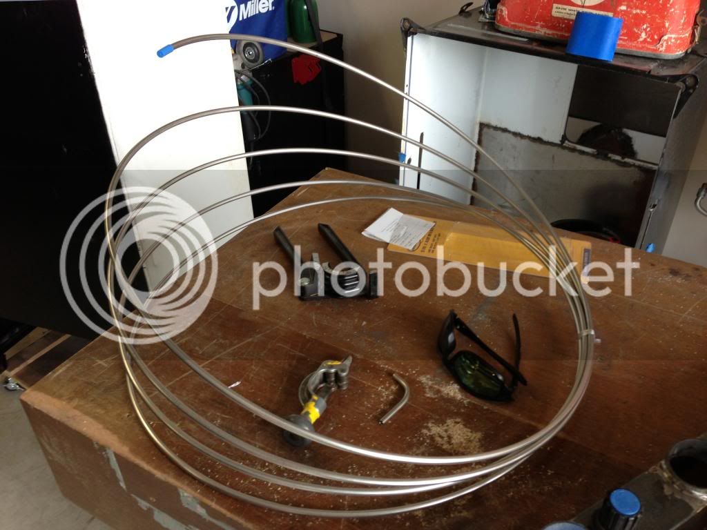
How do you straighten that tubing? There is a lot of material on the net, mainly from hot rod types, on how to do this. I've heard wacko stuff like roll the tubing between 2x4s in your hands, uncoil it into the corner of the garage floor and wall using your feet... All of which don't give straight tubing or that "factory" finish that I mentioned.

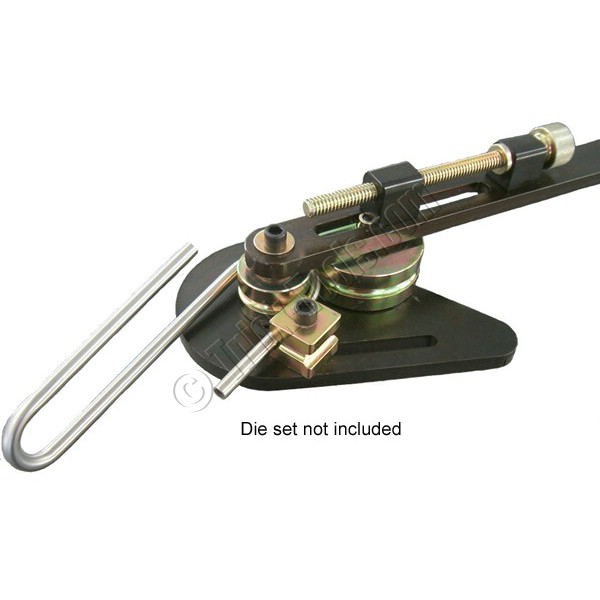
So, my inspiration was the $2-300 tubing straighteners that you find online. The goal was to build one for about $20 and have it be expandable for different sizes of tubing down the line. Easy. :lol_hitti

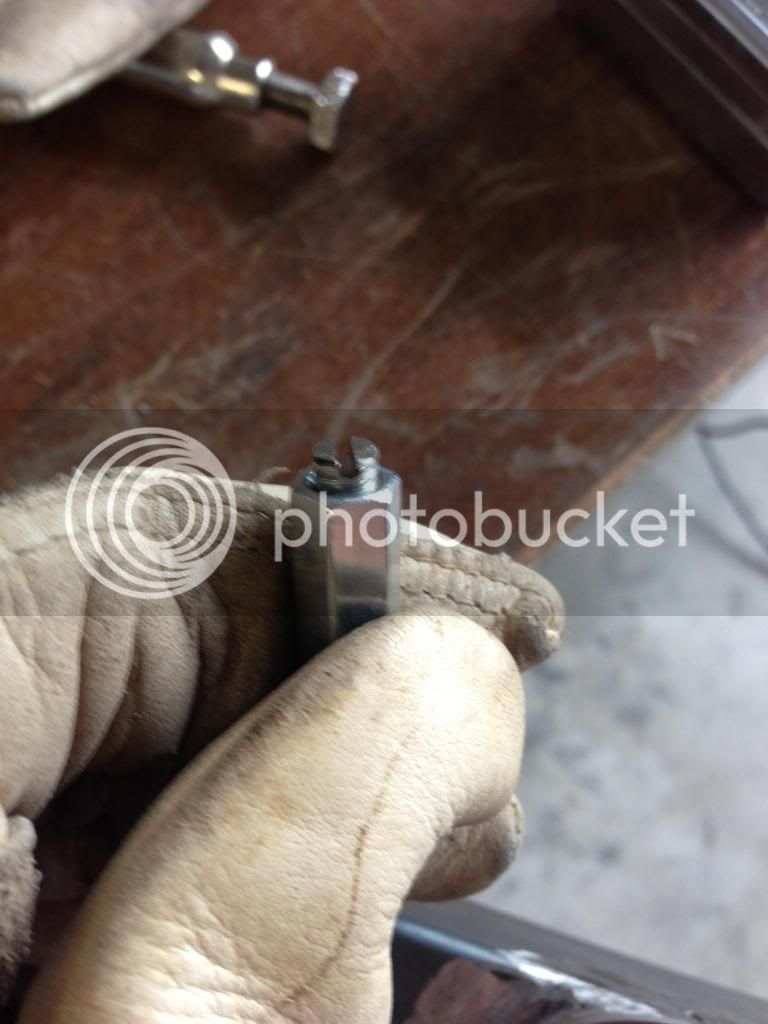
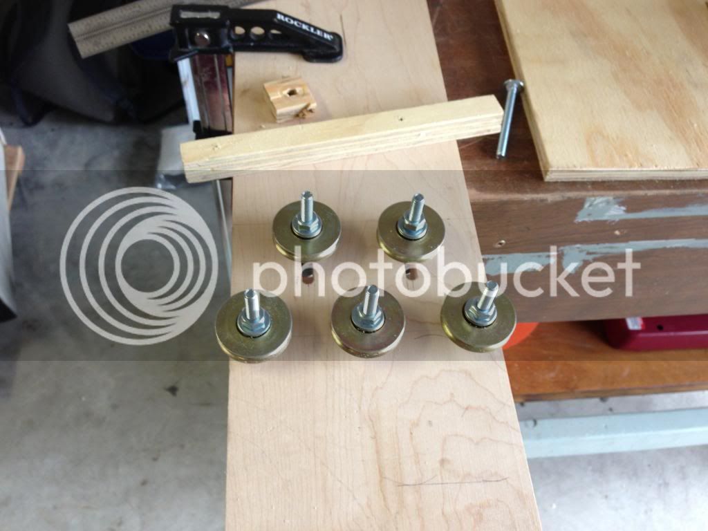
Enter the roller. From a glass door kit.


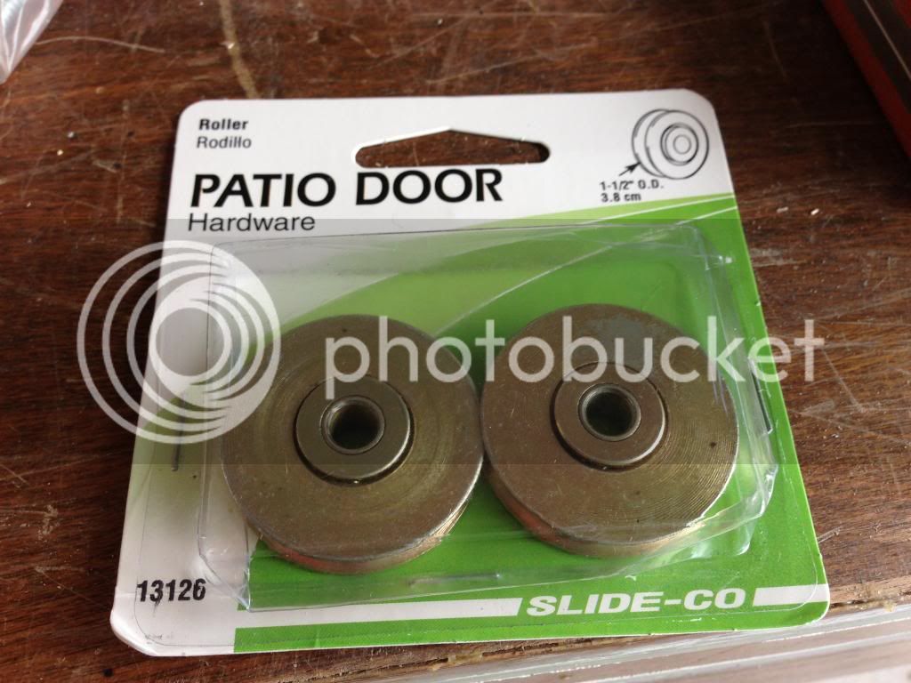
They are 1.5" diameter wheels, ball bearing action. They have a little bit more slop than a pro rig would have, but they were about $3 per pair. I bought 3 pair. I bought them from Amazon, about half the price of a large orange store in the area.

Grab some hardware from that orange store, (story on that to come) and some hard maple from the scrap bin. Lay everything out with a piece of stainless that I bent up with my crappy 3in1 tubing bender. Looks OK.


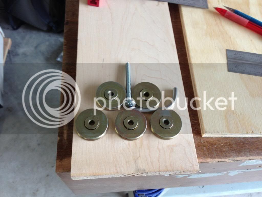
I bought 8 1/4"x2.5" carriage bolts, two packs of washers and nuts, some captive nuts and some all thread couplers just for in case. Long story short, the carriage bolts were from the bulk bin, no tag. The cashier charged them to me as 5/16" split washers. They rang up as 1 penny more than the bolts that they are, but I figured 8 cents wasn't worth me lecturing someone on the difference in a washer and a bolt. Oh America....:dunno:

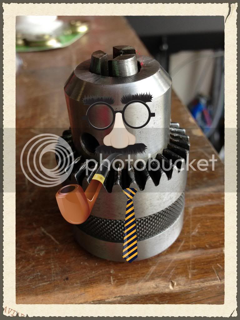
Drill some holes. Here's a trick I picked up last week while reading about drilling straight shelf alignment holes in cabinetry. The problem is getting them square without using a drill press. I had the same problem. I've chased the horrible runout on my drill press to the chuck. I used the marker test. I don't have a nice dial indicator with a magnetic base.

Bad chuck. Bad.


Oh yeah, the trick. Use your router to drill the holes. I have a plunge router and a bit that is exactly 1/4". Now, a nice spiral upcut bit would have been better, but my cheap-o straight 2 flute bit worked nicely. No egg shaped holes, perfectly square to the surface. I set up a temporary fence using scrap and some clamps for my centerline. It is imperative that the holes are all in the same plane or else you will coil your tubing instead of straightening it. I used my Incra rules to measure the offset of the bit to the router edge, mark the line and "plunge-drill" the holes.

I also routed the sliding grooves for the two top rollers. Similar jig, similar measuring techniques. These aren't as critical, you just want them to be parallel.

Voila.


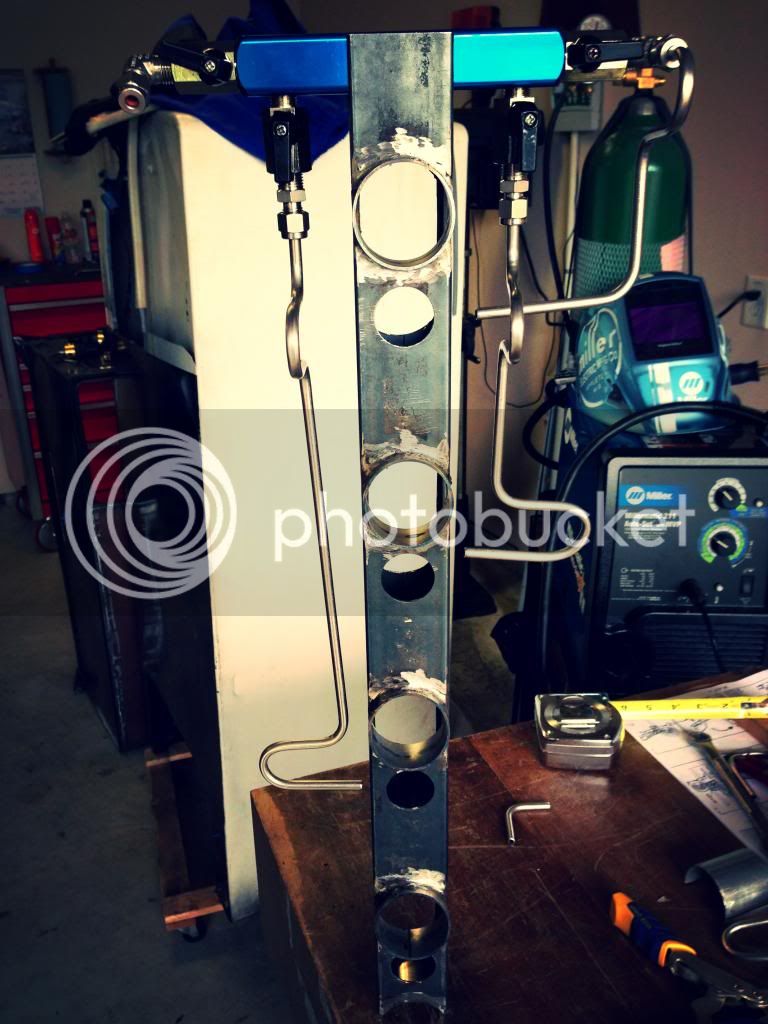
Here's the setup - minus the adjusting bar.


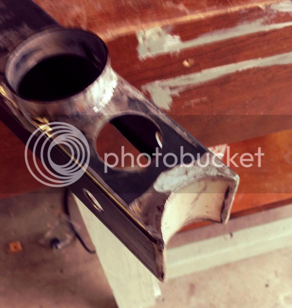
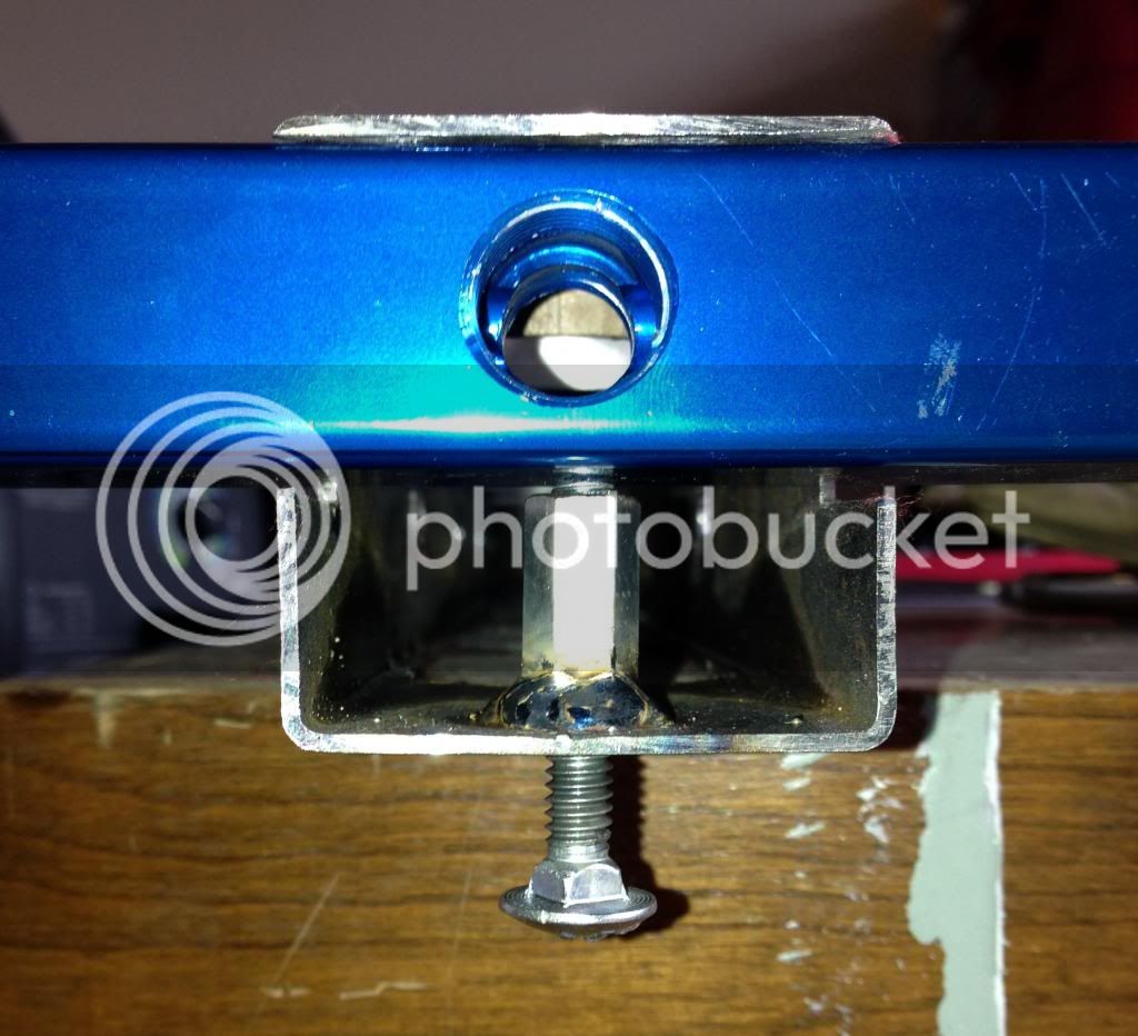
You'll notice that I squared the bottom of the slots to allow for the head of the carriage bolt to not bind in the rounded corners. One could probably use a regular hex bolt for these two. ***Edit - No you won't notice, I haven't uploaded that pic yet.***

Sorry to drag this out, but I didn't finish the slider bar - mainly because I'm thinking of changing the design. Note to everyone making one of these, it would probably be easier to make in steel. I didn't have anything that would work on hand.

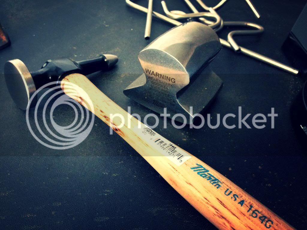
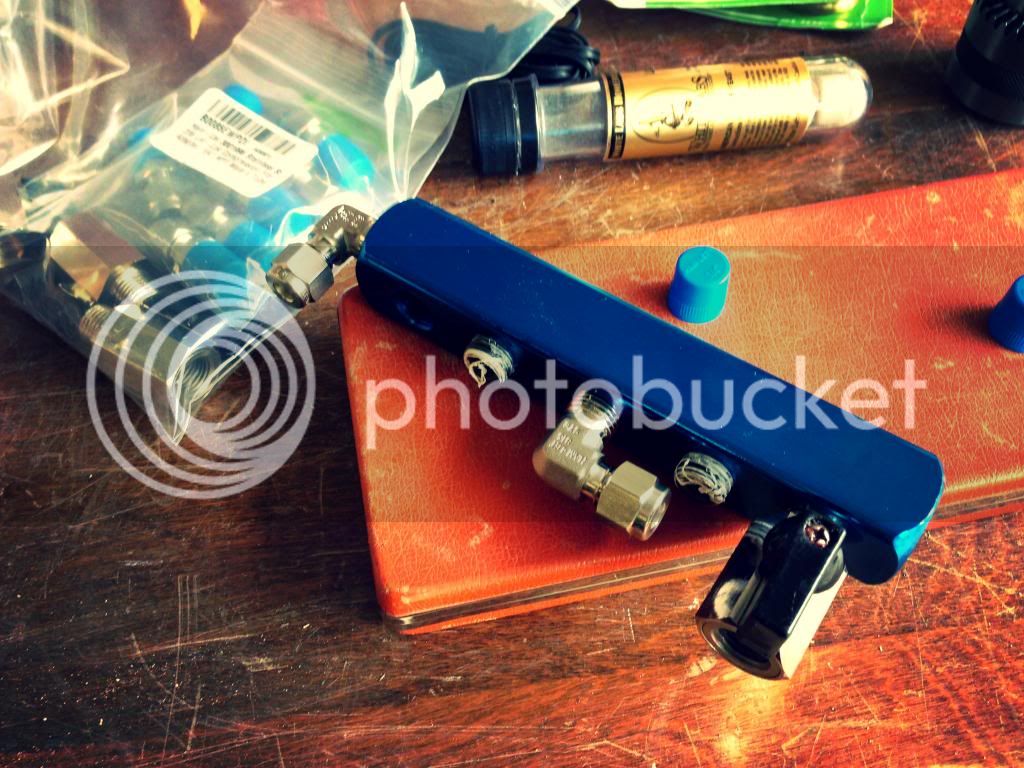
And an obligatory shot of stainless steel fitting goodness...


Stay tuned. Good chuck will make an appearance. Thanks for reading.
 
Only update here is my the completion and testing of my coil tubing straightener. By removing two wheels it can be used to make coils - i.e. for your herms, chillers or whatever. Stop trying to bend these around a keg with your feet and zip ties. $20 - perfect uniform coils.

First I cut down some aluminum angle 1.5"x1.5" with the jigsaw. A band saw would have come in handy right about now. Then I blocked it all up in the drill press and drilled a 1/4" hole.


A carriage bolt was cut down for clearance. On the final product I ended up cutting off the entire head (see below). Here's where I'm not satisfied with the design. It would have been better to drill and tap this for 1/4"x20. Would have solved a ton of problems in one step and made it easier to build.

I don't have any taps and I'm suffering for it. Instead I needed the cross brace to be tapped and the sliding bar to be held captive but still allow the screw to rotate. The second problem with doing that is that I wanted to be able to take it all apart. I could have just welded a nut above the slider and problem solved. Instead I double nutted it and lost some clearance in the process. Moral of the store - drill and tap it next time..


Above, you can see how I ground down the carriage bolt for clearance. I also drilled an access hole just in case. I love using nice sharp Forstner bits. Note the tearout from chiseling the slider tracks out. Whoops.

The final product. I double nutted the top with a washer inbetween so my wrench could sit on it and not slip off to allow for quick adjustments. I think I may make a handle from maple once I can think of a simple way to attach it. If anyone has ideas, I'm all ears!


The first pass was pretty easy. I just chucked it up and then tightened the rollers another half turn. Then I pull the coil back until the end was at the last roller and began to push it through. Didn't take much effort at all.


After about 4 passes this is the result!


Next thing to do is cut the bolts down and give it some paint.

A couple of tips for anyone wanting to make one of these:

Get nylon rollers if you can find them. I got a few scratches on the tubing from these steel rollers. I'm not sure how because they are quite smooth.

After straightening the tubing in the "hard" direction, roll it to take out any curve from the natural helix shape that the coil is in.

Next I'll post up some stuff on bending the tubing and using the compression fittings if anyone is interested.
 
Keep it coming. I am interested in seeing this finished.

Must be the only one reading :D

or at least posting!

Just a small update on the bender. I spent the first night staring at parts and scraps and swatting mosquitoes. What an efficient use of my time.

I was trying to create something like this from wood and carriage bolts:

hb1.jpg


It just wasn't coming to me. No surprise. I was befuddled by the bolt head sticking through the roller and causing interference with the carrier body. I finally decided to just wing it and not lock down the roller to the swinging handle and just let it slide loosely over the frame.

I grabbed some soft fir and drilled holed 1.5 inches apart (roller radius (0.75" x2 rollers). I clamped in a peg to hold the tubing and tried to roll it around.

It didn't work.

I immediately saw why the roller separation on the nice HB1 bender is adjustable. You either need to be able to drill very accurate holes and have very accurate bearings or have an adjustable slide.

I needed an adjustable slide. More work for me. Those $70 single tubing sized benders aren't looking so bad. I also determined that I needed a way to capture the roller rigidly to the arm. I was drawing a blank so I went inside and looked through some designs on the internet.

This is what I found:

rdb10-manual-bender.jpg


It's obvious. Make the carrier frame the same size as the inner roller. Then a nut sticking below the outer roller can traverse the entire arc without interference.

Here's what I got done before the wife got home:


I really want a piece of 1/4" aluminum for the handle. It would make it more compact and much sexier.

Here's to some more progress :beer:
 
LOL - thanks. Rolling the tubing won't be a problem. As cheap and easy as this is - everyone should have one.

I'm certain mdf would work great if you didn't have some expensive hard maple around. I'm still looking for a smaller diameter die to use to make tighter bends. Might buy some plastic blanks this weekend and set up a mini lathe with my drill press and router... Could get interesting.
 
Made some progress on the tubing bender. Here it is in it's rough form right before making a test bend.


Here are the results:


I'd call that a 180. Not bad for $4 in parts. After a little spit and polish here is what the entire package looks like:


spin_prod_221357101


Come on now, you didn't think I could live with those bends? It crushed the tube into some oblong cross section. Can't have that can we? Went to Sears and picked up this bender for $40. Probably worth the time and effort to get great and easy bends.

Can't win them all I guess.

To get started bending I added all of the jewelry to the Christmas tree. That's a nickname in the oil field for the string of gate and ball valves at the head of the well. Think the part that broke on the BP oil spill... With all of the valves, manifolds and regulators I thought it would be appropriate. Here she is all dolled up:


The manifold is just clamped in right now because I'm not quite sure how to attach it. I'm thinking of using a set screw in the back to clamp it against the front piece.

Now, to get to the meat of all of this tool making... Oh yeah, cut me some slack - my first tube bending experience. I'm not thrilled with how it turned out and may swap out the 90 degree fitting for a straight one and just making 2 90* bends. I'll maybe use the 90 in the other valve, make a 180 to go over that first inlet and make a run to the next.

The whole reason I did the 180 was because I could not for the life of me get a Z bend that would drop the tube 3/8". It just looked like crap and the bender wouldn't do it. If there is a tube bending expert reading this - please chime in - I'm open to any suggestions.

Enough talk - here it is:


The gauge face has blue tape on it to protect the plexi. Only took 2 screw up pieces to get this one done... Not bad :beer:
 
And now you're going to get me all interested in upgrading my kegerator...
 
Little bit of an update here, sprinkled in with some tool goodies...


Finally kind of figured out this tube bending thing. Still miscalculating my lengths when I make my cuts - so like most guys - I overcompensate and add a few inches..

I'll start with the goodies. Spoiler alert, I'll be reposting this in the tool section too.

Browsing Craigslist while in a training session at work I came across an add for some vintage tools. Couldn't pass up the deal and the guy actually worked a few blocks down from me.

Paid $50 for these two boxes. It's great that they are still in their original boxes.

Boxes_zps0ae00b86.jpg


The one on the left is a set of Wiss-17 snips. Never been used and still in the wax paper with cosmoline on the blades.

Snips_zps15c68a12.jpg


And the greatest prize is the one on the left - a Parker Kalon No. OX sheet metal punch. Patented in 1915! I've found a few other sets for sale and have heard that it will punch up to 14 ga. steel!

Punch_zps9adb502c.jpg


Onwards and upwards - Had to do some retakes but I'm finding my way with the bender. In a bout of frustration I pulled it all out and decided to finish out the bottom of the tree.

I still cannot get my hole saw to cut true and straight. I'm pretty sure the arbor doesn't let the saw sit square and flush. DeWalt brand if it matters to anyone. This resulted in me cutting the other scallop with the grinder - which sucked. I cut the pipe down to size length-wise first. Then I tacked it in the cutouts making sure that it was flush with both faces. I used the square tubing as a guide to cut off the round tube. Welded it in, ground it flush and then in a stroke of brilliance I squared the bottom in my dry cut saw. Here's the blurry result:

Xtreebottom_zpsfa9d9fba.jpg


Decided to finally fab up the manifold mount. Started by squaring the cutouts with a file. Always a good time to be filing steel in 90% humidity. I decided to just use some kind of set screw to clamp in the manifold.

I used a 1/4"-20 all-thread coupler as the main piece. Ground it down a little bit to fit and then welded it in with a bolt in place to ensure that it was square.

ManifoldRetainermockup_zps640f2275.jpg


Of course I don't have a nice allen set screw so I cut down a bolt and then ground a slot in it to create a groove for a flat screwdriver. The trick to it was that I screwed in the short piece (set screw) and from the other side tightened up a longer bolt to keep the short piece from rotating while I cut the groove.

Note the gloves - safety first!
locknut_zpsad3431e5.jpg


And finally a glamour shot of the empty tree with some of the bent tubing hanging off of it.

Xtreelines_zpsc9335d66.jpg


Thanks for reading, I hope everyone has enjoyed it as much as I have.
 
Finally back after a hiatus of working on the cube table, building a power supply to make an electrolysis tank, and starting a new job. Fortunately that one left me with a week at the house to get some fab time in on the kegerator.

First things first - I reworked the regulator tree. I didn't like how the tubing outlets from the distribution block were not lining up with the regulator inlets which forced the tubing to have some freaky bends. In the v1.0 configuration I also could not assemble the gas-in line, it just would not physically fit. To summarize, I made the slot wider, slid back the dist. bar, and re-did most of the lines. Little bit cleaner now, I think. I also had to run the left most line really tight to give me as much clearance as possible for the kegs. Despite this, I still ended up adding 10.5" vs. 6" planned.


Now the big decision came - the one I've been dreading this entire build - cutting her in half. I was/am nervous about welding it without oil canning it, and I didn't like my plan for cutting it at the back to avoid forming the sheet would have been a design flop. I bit the bullet, bought a bead roller and a big abrasive blade and went to town.


The worm drive Ridgid is a beast.

I laid out my cut lines with tape, working with the box being out of square as best I could. First attempt at a straight edge involved bar clamps and a wooden guide.. It didn't work. I slept on it and kicked myself the next morning that I didn't think to tack the straightedge to the shell. Duh.


Nice and sweet 1/8" cut.


Repeat 4 times and you get this...


An inner fridge shell bifurcated. Let the fun begin.

Got myself some 18ga. carbon steel at a local sheet metal fab shop. 40' of 10.5" wide strips (4x 10ft pieces) was about $100. Great deal. Perfectly square using their nice big shear.


The gauge is hanging off some test strips I cut up to determine the best welder settings and to test the panel clamps I finally decided to buy. Lot of decisions to make when deciding to weld up long runs of flat sheet, but I decided that the clamps would help me keep it square and both sheets in plane -the longest run will be nearly 5 foot of weld..

Gapped at 0.04in. I put the veniers on them and found them to have a +/- tolerance of 0.003in. Not bad for HF.


Thanks to the guys here (Robert) and at allmetalshaping.com for tips on fitup and hammer planishing the welds.

Here are the shapes that need to be made - an approximate 1/4" radius bend, and the panel inset.


Got lucky and had a router bit and some maple to make a forming buck with.


Test piece tipped over with just a ball peen hammer, Estwing of course :willy_nil.

Shot of the setup I used to keep everything in line while creating the bend. Nothing too fancy here. I started with a 7/8" stickout, which ended up being too much. 1/2" should work fine next time. It's probably worth mentioning here that I decided to build it in 4 pieces and weld the "corners". My plan is to tack each piece to the back shell, tack the corner seams, then tack on the rest of the shell so that I can keep it all square as I go. I anticipate the need to add bracing bars.. One last decision is whether or not to add some stiffening beads - wish I would have thought of it earlier because the filler piece isn't in the exact middle, and I'm not sure I can bead roll over the ceramic/porcelain coating on the existing metal.

Final product.


And the final mockup.


I wasn't sure how to measure and layout the second corner so I just put the wooden buck in the original frame and clamped it to the new piece, pulled it all out and made a wild guess. Worked out perfectly.

Phase II will actually start with me beefing up the bead roller and possibly making some dies so that I get the raised panel bit correct. It's at an odd angle, but I'm new to panel rolling.

Thanks for reading.
 
So maybe I missed it somewhere, but now that you have expanded the inner cabinet, what's your plan for the outer cabinet? Will that be expanded as well? I have a similar fridge and the space between the cabinets all around is about 3".
 
So maybe I missed it somewhere, but now that you have expanded the inner cabinet, what's your plan for the outer cabinet? Will that be expanded as well? I have a similar fridge and the space between the cabinets all around is about 3".

You are correct, there is only about 3" of dead space in mine as well. I plan to stretch the outer shell by the same amount, 10.5". I will build an adjustable "floor" support for the inner shell to accommodate for the increased depth and weight. I wish I could have gotten away with only stretching the inner panel, but, c'est la vie!

Not mentioned yet, but the bottom trim panel will be converted to a full extension drawer with a cutout for the compressor. The support structure for that drawer will also house castors and the previously mentioned support arm.

Thanks for asking, happy to explain anything.
 
Small update today:

Finally back in town after a 3 week hiatus saving the world in California. Gave me some time to track down and buy these from Summit Racing:

IMG_05251_zps1b6d71cd.jpg


Oh yeah, hammer was about $25 and the dolly was around $40 I think.

Many thanks to the guys at allmetalshaping.com for recommending them for planishing. Proves you can still learn something every day. Hammer feels a little lighter than I'm used to, and I wish the handle were a tad longer, but the fit and finish are great. The dolly could use a minor buff and polish with a DA, but it's pretty nice overall.

I got the cheap-o HF bead roller to roll out the 18ga. quite nicely. I had to weld some square tubing on the side to clamp it to the table, but I got a nice test piece done that actually matches the contours I need. I was really worried this wouldn't work out. I ended up using the 1/4" panel raising die and offsetting them a bit to get a nice "Z" bend to match.

Here's the test piece beside the fridge inner shell. It's hard to tell what you're looking at, but it all lined up after three adjustments to the machine. I'm going to roll the big piece when I can convince the wife to crank the wheel for me...

IMG_05261_zpsaa1132e1.jpg


Lastly, here's the progress so far, tacked up and with a 3/8" square rod to hold it all together. I've got a concern that the panels aren't square and parallel, but it will be tough to determine until I get the other side mocked up. The metal wants to bow and sag under its own weight, so having the other shell on there will allow me to figure it all out.

IMG_05271_zpsb098b19e.jpg


I've thought about rolling a bead in the new panels, but just can't bring myself to do it because I know I'll roll them crooked. I'll probably just tack on some straps on the back to make it a bit more rigid.

Thanks for reading. More to come this week.
 
I got the wife to crank on my handle (bead roller handle gutter brains) and got the raised panels made for the top piece. Wasn't too hard, there's a slight wobble in it that I can blend out easily with the high build primer.

The panel heights are not quite perfect, but all of the contours were coaxed a little with my new body hammer. Anyways, here's how I laid out the "beads."

Roll the first one while leaving enough overhang to trim it all up later. You want some extra meat to cut of because of the shrinking/stretching happening when you roll the panel into it. That's a tip I learned from some old experts. Then I just worked my way down the panel, marking the bends from the "template" onto the blank piece. Once all four were rolled, square up the pieces and clamp everything down.

Scribe/mark the backside for cutting and get to work. On the pic below, notice the overhang on the left and right.

IMG_05291_zpsbdb0b48c.jpg


Once it's cut out, clamp it all back down and start tacking. I ended up busting some old tacks and closing up the gap a tad. Once the box was cut apart it let go of its internal stresses and bowed back a little. I used some F clamps to bring it all back into alignment. Also had to massage the corners a bit and radius the inner "panel" to get better fitment.

IMG_05311_zps88eb7cd5.jpg


Closeup.

IMG_05301_zps5381f3e7.jpg


Below is a shot of the entire box turned upside down and from the inside (the panel is the top from which the freezer box is hung). I think you can better see the contours of the raised panels and what I was trying to do.

IMG_05321_zps2e999db3.jpg


Originally wanted to just section it behind the panel, but I'm happy I went this route and bought/learned how to use a bead roller.

Thanks for reading, hope you are getting as big a kick out of this as I am. Everything I've done is with inexpensive tools and more or less my first time at it all. Anyone can tackle a project like this with some patience and YouTube!
 
I guess this Bud's update's for you, Stealthcruiser.

Howdy all,

Little bit of work today - after all, you don't want to over-do it.

Got the bottom panel made and fitted. Same procedure as before, but with only one panel to "raise". I had trouble getting this one square. I wobbled on my cuts, so I tried the hand shears, they bowed the crap out of the flange, so I had to dolly it all back as straight as I could. Moral of this story is that I need to get a shear.

This is actually the bottom - it's just flipped over.

IMG_05331_zps6efe5fe2.jpg


Below is the "new" inner shell. The white box in the background is the original fridge box as a reference for how much this thing grew. It's more the size of a modern fridge now. You can just reach the back of it without straining. I don't see this being fun welding up and even less fun planishing.

IMG_05341_zpsfd20e2a2.jpg


So now I didn't have a plan except to start at the top, flip it over, and tack together to bottom, leaving the sides for last because there are no features to line up. Again, the clamps were a huge asset, along with some magnets and the new body hammer.

IMG_05351_zpsd84d4aa4.jpg


And done. I haven't planished anything, and there is a bit of shrink on one of the sides that is trying to oil-can. My main concern is the panels being welded together perfectly in plane. On such a long flat surface it would be easy to have them butted up at an ever so slight angle. Luckily only one side is visible and I can massage any imperfections out.

IMG_05371_zps449b4cf1.jpg


The whole deal. Not that exciting but a major project milestone for me.

IMG_05361_zps5131c7db.jpg


Thanks for checking it out.
 
Back
Top