Can Someone Explain This PID Test

Homebrew Talk - Beer, Wine, Mead, & Cider Brewing Discussion Forum

Help Support Homebrew Talk - Beer, Wine, Mead, & Cider Brewing Discussion Forum:

This site may earn a commission from merchant affiliate links, including eBay, Amazon, and others.

thekraken

Well-Known Member
Joined
Aug 18, 2014
Messages
1,957
Reaction score
449
Location
DFW
I'm building a homebrew PID controller for my RIMS tube with an arduino. I was running some tests the other day to calibrate and found that the system doesn't behave like I expected. When I increase the the power output of the heating element, instead of heat slowly ramping up because of 'dead-time' like I would expect it does the opposite! After bumping up the heat the temp shoots up really quickly, then gradually slows and starts to heat at a normal pace. Here is a quick drawing to try and illustrate what I'm talking about:
SeId4cB.png


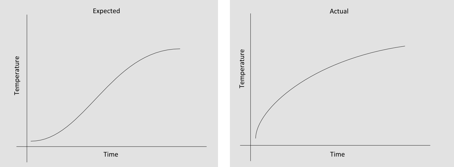
I have no real world experience with this kind of stuff, I can't think of why the system behaves this way vs the way I expected. Can any one enlighten me?

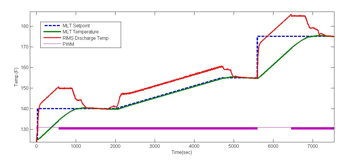
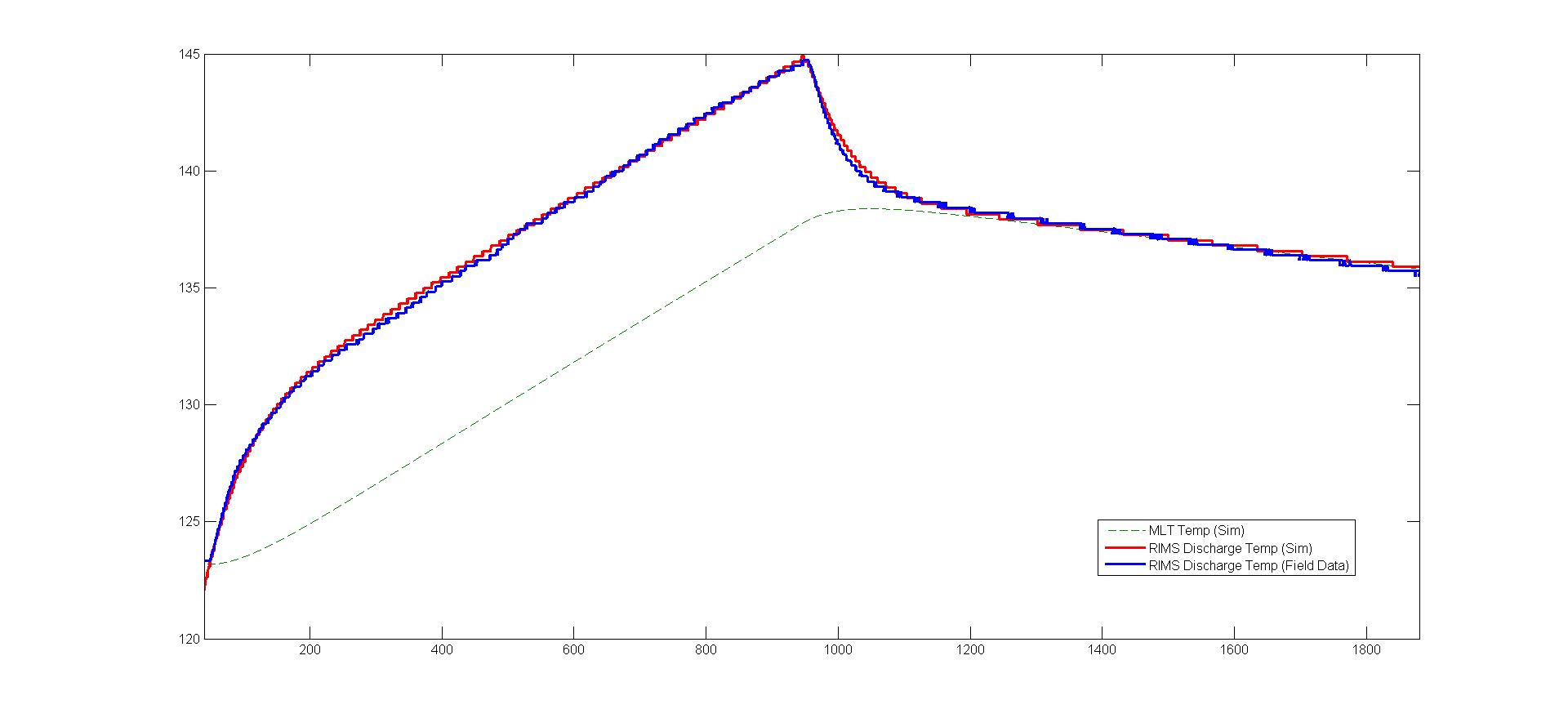
[Edit] These are temp readings taken from inside the RIMS tube 2 - 3 inches from the end of the heating element, after wort has passed over the element.
 
Looks like a standard 1st order step response. So basically your stepping up your wattage instantly and all that energy is going into the system. Initially the energy is used to heat the element but there isn't much mass to the element so it heats quickly... as it heats up, more and more heat gets transfered to the fluid until an eqilibrium is reached.

If you had a heating element with no mass, the water would instantly heat to the final temp (assuming no heat transfer to tbe rims tube) .
 
Ahhh. *light bulb* makes since now.

And a quick google search on 1st order step response and it looks like I got plenty of material to study up on. Thanks BigBlock for pointing me in this direction.
 
Glad that was somewhat helpful... 1st order response can be used as a quick and dirty way to characterize a system in many cases. there are many variables that impact system response to take into account on any given system. Often times several of these factors are negligible. Here's a quick list off the top of my head:

  • Actuator (effector) response
  • thermal/chem/mech/elec response
  • Transport delay (how long does it take the heated wort to travel from the element to the sensor)
  • sensor response
  • Sampling rate
  • Interframe delay (time from when PID reads the sensor to when it finishes calcs and drives the output)

For your system the only lags that probably are applicable are the thermal response and the sensor response (possibly transport lag but it sounds like your sensor is near the element) as long as you don't have any "delay" commands in your Arduino code :)

I'll be doing something similar with a plc but will be calculating how much heat I need to add based on flow, incoming temp, and target discharge temp. (I will need to characterize my flow vs pump speed). Then I will have a slow PI loop with limited authority to slightly trim the power so that the temp is right on the money.

I might even have a simple matlab model to play with if you're interested and have access to matlab/simlink.
 
I know you weren't exactly asking but I'll try to fill in the blanks here in case you can give me tuning advice/tips.

  • Actuator (effector) response
  • thermal/chem/mech/elec response
  • Transport delay (how long does it take the heated wort to travel from the element to the sensor) - This would require some figuring, but the flow measured at the 1/2" output of the RIMS tube was 2gpm, the RIMS tube is 1-1/2" diameter, the flow over the heating element is 12" long, distance from tip of element to tip of the thermowell is about 2.5".
  • Sampling rate - 5 Seconds
  • Interframe delay (time from when PID reads the sensor to when it finishes calcs and drives the output) - ~800 ms

As for actuator and thermal/chem/mech/elec response... I don't know. My system is time proportion controlled, on/off control outputting 1375 watts for some % of 5 second cycles.

[Edit] I went back and crunched a few numbers and came up with a transport delay of about 3.5 seconds, just an educated guess as I'v never done this calculation before.
[Edit x2] That was how long I figured it takes to heat the wort and get to the sensor. From the tip of the heating element to the thermowel is about .7 seconds
 
For your system the only lags that probably are applicable are the thermal response and the sensor response (possibly transport lag but it sounds like your sensor is near the element) as long as you don't have any "delay" commands in your Arduino code :)
Nope, no delays used here. I've found the JeeLib schedule class to be very convenient regarding timing everything.

I'll be doing something similar with a plc but will be calculating how much heat I need to add based on flow, incoming temp, and target discharge temp. (I will need to characterize my flow vs pump speed). Then I will have a slow PI loop with limited authority to slightly trim the power so that the temp is right on the money.
In the beginning of this project I imagined I would have these onewire temp sensors everywhere I could put them to do like you described. I've since decided to personally "KISS" otherwise I would never get it finished.

So you are estimating a flow rate based on pump speed? How are you controlling the pump then? solenoid or pwm?

I'm using one of these cheap flow meters and am quite happy with it. So far, after calibrating it, I've found it to be more than accurate enough for my needs. I did have to spend a lot of time convincing my self that the alcohol I'm making will do more damage to me than anything this non-food grade meter might leach into my brew.

I might even have a simple matlab model to play with if you're interested and have access to matlab/simlink.
I don't have access to matlab, do you think it would be easily portable to sagemath?
 
I feel like I'm sending you on a wild goose chase :)

You don't really need to calculate all you lags unless you're putting a model together. You're probably better off just testing/tuning on the actual hardware.

Also are you using a zero cross SSR to control the heating element? You could probably get away with a shorter time cycle than 5s. I'd go down to 2s with a min pulse of .1 sec (would be about 5% power with up to ~1% error). Less temperature variation and longer heater life.


Following up on other Q's:

Looks like there's not an easy port from simulink to sagemath. Anyhow I just opened my model and its incomplete so no loss there.


I'm still working on my automation build, but I have a VFD and the 1/8hp 3ph motor for the pump arived a couple days ago. Have not ordered the pump wet end yet. I'm planning on running it at multiple power levels and draw up a curve of VFD freq vs flow. Won't be perfect but will get me within a few degrees and the PI loop will tune out the residual error. Also, since it calculates the power setpoint based on flowrate, it will react fast if I modify flowrate. Have you had any clogging issues with your flowmeter?

I also have one of the $20 ebay 24V pumps that I'm going to play with PWM via a DC SSR if I get time. Just trying to get my initial panel wiring complete and punching/soldering the last fittings in my pots right now. So many parts, so little time.
 
Yep, I'm running this zero cross dual SSR.

Ill scale back my cycle time then and see how it goes. Can you elaborate on getting longer heater life by doing this?

Ahah, so you'r not going the typical march/chugger pump route. I've thought about getting one of those ebay DC pumps too, if only to cut down on the noise, automated flow control would be nice too.

[Edit] Oh no I take that back. My relays are random turn-on, not zero cross. Would you still reduce the cycle time?
 
Typically heater life is dependant on thermal cycling. The less it cycles and the smaller the magnitude of cycling the longer the life of the element. My experience with band heaters and may not apply here. Practically speaking your brew setup probably won't run enought to worry about cycling but its a side benefit of tighter control.

As for the ssr, the main reason you want a zero cross is to reduce noise. Especially if you are using an arduino which I would look into getting a zero cross. can't say it would def be a problem but something to watch out for if you try the one you have
 
As for the ssr, the main reason you want a zero cross is to reduce noise. Especially if you are using an arduino which I would look into getting a zero cross. can't say it would def be a problem but something to watch out for if you try the one you have

I've used this ssr now for a couple brews and a bit of testing, it hasn't presented any problems yet. What could this noise do? Unintentionally fire the element? I am also using a current sensor on the whole system to monitor and make sure I'm pulling an expected amount of current at any given time if that makes any difference in this regard.
 
I've used this ssr now for a couple brews and a bit of testing, it hasn't presented any problems yet. What could this noise do? Unintentionally fire the element? I am also using a current sensor on the whole system to monitor and make sure I'm pulling an expected amount of current at any given time if that makes any difference in this regard.

I'm not an expert in this area but in general....Electrical Noise ( when a conductor is placed in a time-varying electromagnetic field, a cur-
rent is induced in that conductor) can cause issues, especially on communication and analog I/O lines. The result could be lost packets, reduced data rates, erroneous analog readings, erratic 1 wire issues etc. On the job all our control wiring is shielded twisted pair, and is never run along with AC power lines. Since our hobby implementations typically use basic unshielded wires we would be more susceptible. In practice at the AC current switching levels and short wiring runs that you're using it may not be a problem. Just noting that every manufacturer recommends zero cross for resistive heating applications. I haven't run into a situation where noise was an issue, but I try to design around it.

If you're really bored a quick google search yielded:
http://www.ti.com/lit/an/snoa382/snoa382.pdf

On a side note I now have a working simple(ish) RIMS matlab model. When you get your system running I can update the model parameters and make a first pass at PI gains.
 
On a side note I now have a working simple(ish) RIMS matlab model. When you get your system running I can update the model parameters and make a first pass at PI gains.

Hey, awesome! What information would you need?

I have recorded data from two step tests. The first test was from 10% to 100% duty cycle over a short length of time, the second was from 15% to 35% duty cycle over several hours. Obviously the first one never leveled off as I wanted to end it before the temp rose to high. I ran out of time on the second test and it never quite settled, but it came close (I think).
 
Right now I have the RIMS heater and MLT modeled. MLT is just a simple volume of water at same temp (did not try to model stratification) with heat loss from the kettle to ambient.

Inputs needed:
  • Kettle height
  • Kettle diameter
  • Flowrate (I’d just time how long it takes to fill 3 gallons with a stopwatch)
  • Heating element wattage

Here’s a test that would be helpful to run:

In a perfect world I’d like to have temp measurements at the inlet and outlet of the RIMS heater, or MLT temp and RIMS discharge. If all you have is the RIMS discharge I can work with that.

Open loop response test
  • Fill MLT with 3 gallons of hot tap water (100-140)deg
  • Start recirculation
  • Start data recording (probably best to sample in the .1 second range to keep the file reasonable) Record temperatures and heater output
  • Run heater at 100% power for 15 mins then turn off
  • Continue to record data for another 15mins with no power but recirc still running. (I would like to see a few degrees of temp drop prior to stopping data collection)

With that data I should be able to quantify the heat transfer coefficients, overall system response, and first pass at a tune. Please include a link where I can DL your data or shoot me a PM and I’ll give you an email address to send the data to. If you want to send what you already have it will be helpful too.

Will do, the only issue is the 100ms sample time you've asked for. I'm using the dallas ds18b20 onewire temp probes, at the resolution setting I'm using they take about 750ms to convert and return a temp reading. I have no idea what kind of sample rate leads to 'self heating' with these things either, I'll defer to your judgement.

[edit]
I've been using the highest resolution, 12 bits. From the ds18b20 datasheet:
Resolution, Max Conversion Time
9, 93.75ms
10, 187.5ms
11, 375ms
12, 750ms
...
The resolution of the temperature sensor is user-configurable to 9, 10, 11, or 12 bits, corresponding to increments of 0.5°C, 0.25°C, 0.125°C, and 0.0625°C, respectively.
 
Good point, lets go with an 11bit A/D (375ms)as a compromise. Should give enough data points during the transient and enough fidelity to curve fit. You still want to sample around the original 100ms rate to minimize as that still adds delays on top of the ds18b20.
 
Open loop response test
  • Fill MLT with 3 gallons of hot tap water (100-140)deg
  • Start recirculation
  • Start data recording (probably best to sample in the .1 second range to keep the file reasonable) Record temperatures and heater output
  • Run heater at 100% power for 15 mins then turn off
  • Continue to record data for another 15mins with no power but recirc still running. (I would like to see a few degrees of temp drop prior to stopping data collection)

Okay, took some rewriting but I should be all set up to record temperature data at 400ms intervals. What format would you like the data in? CSV, Excel, openoffice, sqlite?

Would you like me to start at say 10% and allow the temperature to stabilize before I step up to 100% power?

Finally, I'm doing full volume, no sparge mashes so in practice I'll have 6.5 to 7.5 gallons of recirculating wort. Even though it's a water test without any thermal mass from the grain, should I do this test with 7 gallons of water? Or does it not matter?
 
Okay, took some rewriting but I should be all set up to record temperature data at 400ms intervals. What format would you like the data in? CSV, Excel, openoffice, sqlite?

CSV file is simplest. I can do excel or openoffice as well.
Just to clarify... you have the ds18b20 sampling at 400ms, but the arduino is writing values every 100ms to the *.csv correct?

Would you like me to start at say 10% and allow the temperature to stabilize before I step up to 100% power?

Nope, just get things circulating and run it wide open. That will provide a system step response that I can validate the model with. We aren't trying to do any control or represent how you will actually operate it.

Finally, I'm doing full volume, no sparge mashes so in practice I'll have 6.5 to 7.5 gallons of recirculating wort. Even though it's a water test without any thermal mass from the grain, should I do this test with 7 gallons of water? Or does it not matter?

Same idea here, I'm just trying to dial in the model. I chose 3 gallons as a minimum, but 7 would work even better if thats what you typically use. Make sure you use hot (~120+)water though. I'd like to quantify the heat loss from the kettle/piping to the air. If the kettle is about the same temp as the ambient air we don't get that data.


Looking forward to seeing the data. If my fittings would hurry up and get delivered I would give it a try myself, but unfortunately it will be a few more weeks on the slow boat. I should be able to tune the model quickly once I have the data. Then we'll have to figure out how exactly you want to control the temp. Right now I setup the controller to control to the MLT temperature with a secondary PI loop that limits the max temperature rise over the RIMS to prevent scorching. Let me know what you're thinking and I can start coding the arduino function.

If you have a pic of your setup post that up as well

I wonder if others are reading this thread and thinking... "wtf, we're just making beer right?" :mug:
 
CSV file is simplest. I can do excel or openoffice as well.
Just to clarify... you have the ds18b20 sampling at 400ms, but the arduino is writing values every 100ms to the *.csv correct?

At the moment I'm only recording data points every 400ms since the fastest the temp probe can get back to me with a response. Anything between samples will just return duplicate data. I can fill in those blank spots if you need it for your script. As far as I know the sensor will only handle one request at a time. Or should we crank all the way down to 9 bit with a resolution of 0.36F?

I wonder if others are reading this thread and thinking... "wtf, we're just making beer right?" :mug:

Nahhhh :mug: Over engineering things has with out a doubt been the most enjoyable part of this hobby for me. My beer may not taste the best but damnit I'm going to look good brewing it!
 
At the moment I'm only recording data points every 400ms since the fastest the temp probe can get back to me with a response. Anything between samples will just return duplicate data. I can fill in those blank spots if you need it for your script. As far as I know the sensor will only handle one request at a time. Or should we crank all the way down to 9 bit with a resolution of 0.36F?

If you're code is setup to write the sample whenever you see a temp change/power output change then you're good to go (obviously recording the timestamp as well).

If you're just sampling at a constant rate of 400ms, in the wost case you could be sampling 1 ms before the sensor updates which would result in 399ms delay (from sensor)+400ms delay(sampling frame rate), doubling the delay. So the 100ms sampling rate I suggested would keep the worst case delay under .5sec and keep the data file reasonable. Sorry if this is a duh statement, but I see this all the time in the field when I ask for people to send me trends so just making sure.

Here's a quick trend of the model in action with a couple of temperature steps and a ramp in the middle. I set the max RIMS discharge temp @10degrees above the MLT setpoint. 1200watt element, 7 gallons liquid @0.5gpm

pretest.jpg
 
Oh okay got it, I should be collecting temp readings about 15ms after it's available. I'll be recording millis, temperature F, duty cycle%, and flow rate GPM every 400ms +- a few ms. I'll collect some data this evening.
 
Inputs needed:
  • Kettle height
  • Kettle diameter
  • Flowrate (I’d just time how long it takes to fill 3 gallons with a stopwatch)
  • Heating element wattage

Open loop response test
  • Fill MLT with 3 gallons of hot tap water (100-140)deg
  • Start recirculation
  • Start data recording (probably best to sample in the .1 second range to keep the file reasonable) Record temperatures and heater output
  • Run heater at 100% power for 15 mins then turn off
  • Continue to record data for another 15mins with no power but recirc still running. (I would like to see a few degrees of temp drop prior to stopping data collection)

Okay, I've attached an csv file that I renamed as an xml to get it to upload, you can delete the .xml at the end of the file name. It's three cols in ms, temp fahrenheit, and percent duty cycle.

The temperature readings were taken 2 to 3" away from the heating element, after the water past over the element.

My MLT is a 15 gallon cooler, it's inside dimensions are about 16.25"x14.25"x17.125" (LxWxH). That is the equivalent of a 17.17" diameter by 17.125" high round vessel. The test was done with the cooler's lid cracked open to allow for the 1/2" silicon return hose.

The flow rate was measured at about 1.2 gallons per minute.

I'm using a 1375 watt heating element at 120v. That's specs, I did not measure directly.

View attachment step_test1.csv.xml
 
Thanks for getting the data quick, now I really can't wait to get mine up and running!

Anyway, I was happy with how little tuning I had to do on the model match. Had to tweak heat trans coef as expected. Only surprise was the amount of lag/delay in the system. It took almost 10 seconds for the temperature to react after you turned on the heater. I was anticipating something closer to 2 secs. Guessing a mix of transport delay and thermowell lag. Whats your rims tube diameter?

Here's the results of the model match. Plenty good to brew beer :drunk:

model_match.jpg


Unfortunately I won't have much time this weekend, and theres a good possibility I'll be hung over on Sunday. So will likely be monday before I finish the PI tuning and start coding up the arduino function. If you want to send me your sketch I can work directly from that.
 
Wow, that's a match! It's eye opening to actually see the MLT temp lag behind the RIMS tube, but consistent with what I was sort of guessing it was.

The RIMS tube is 1-1/2" cast pipe. My temp probe is essentially behind 2 thermwells, the first being the case on the cable. There is no kind of thermal grease or anything between the RIMS thermowell and probe. I'm guessing these layers of 'insulation' are partly to blame for the lag time. But like you said, good 'nuff to brew beer!

As far as code goes, I was just planning on using this arduino PID library: https://github.com/br3ttb/Arduino-PID-Library/ It's very simple/straight forward and easy to incorporate into my project. Any comments or suggestions on it?

If you'd like I can definitely send you the code I used to run this test, but it was really just hacked together to get this test done. PM me an email address and I'll send you a zip.
 
Last edited by a moderator:
Wow, that's a match! It's eye opening to actually see the MLT temp lag behind the RIMS tube, but consistent with what I was sort of guessing it was.

The RIMS tube is 1/2" cast pipe. My temp probe is essentially behind 2 thermwells, the first being the case on the cable. There is no kind of thermal grease or anything between the RIMS thermowell and probe. I'm guessing these layers of 'insulation' are partly to blame for the lag time. But like you said, good 'nuff to brew beer!

Ahh makes sense now. Sofor reference, large lags do make tuning more difficult and will lead to a slower overall response. I would definately at a minimum add some sort of thermally conductive material in the thermowell. Ill see how well we can tune it up. thanks for the link to the Arduino library it saves me some time from coding something similar myself. so do you plan on having a temperature sensor either in the MLT or on the return side of the rims tube? if so we can automate the whole temperature process. also let me know what kind of arduino you're using. I'll shoot you an email address so you can send me your sketch. that way I can double check that the sketch isn't too big and we don't run into execution time problems.
 
Last edited by a moderator:
I'm using a knockoff pro mini from eBay. $2 a piece and no complaints.

Ill look into putting a temp sensor on the mlt outlet or more likely the rims inlet. But for now I'm just planning on using the one sensor.
 
so do you plan on having a temperature sensor either in the MLT or on the return side of the rims tube? if so we can automate the whole temperature process.

Alllright, you talked me into it. I'v ordered some fittings that should allow me to put another temperature probe in line somewhere. I'm thinking the difference between MLT outlet and RIMS inlet has to be too insignificant to care which which place I put it... Right? I'm using silicon tubing.

With this probe are you thinking of cascade PID control or just a PID on the MLT probe and use the RIMS probe as a safety/limiting check to prevent scorching and what not?
 
@BigBlock, just curious if you've had a chance to fool around with it anymore?

I was searching google last night for any kind of how to guide or anything on modeling a first order response. Everything that came up was full of calculus and language I really wasn't in the state of mind to mess with last night :drunk:... turns out not very many non-professionals want to model processes for fun. Go figure! I'll have to take a crack at one of these papers when I have a free morning and a fresh cup of coffee.


yeah I've been a bit mia. Wife is out of town and I have the kids so free time is at a premium. That being said, now that you are adding the sensor to the rims inlet I can set up the control more like what I had planned for my system. Instead of cascaded loops which tends to lead to a slower tune, I'm doing a simple model based approach to limit the rims discharge temp while using a PI loop to maintaint the MLT setpoint. Ill shoot out a diagram tommorrow.

Just updated the matlab tonight and I'm happy with the response for a range of flowrates and temps. I may be able to cobble some arduino code at lunch that's close enough to working for you to look through/debug.
 
Here's what the control logic looks like right now....

brewCtrlLogicDiagram.jpg

Okay, so I think I follow: Essentially calculate a power based on a PID running off of the MLT itself, and also a power based on the RIMS tube and MLT delta, then use the smaller of the two values?

I'm curious to see the actual formulas used in the upper half of the diagram.

[Edit]
And thanks for everything your doing! Without you I'm pretty sure I would have wound up using essentially a bang-bang control.
 
Just pinged you some (alpha) code.

As for the calculation, its basically Q = m Cp dT

I enjoy doing this work and helping people out ....but in full disclosure I'll be using this same approach on my rig, so it will be nice to have worked out the bugs prior to implementation on my build. :mug:
 

Latest posts

Back
Top