STC-1000+ PI (the mash control firmware)

Homebrew Talk - Beer, Wine, Mead, & Cider Brewing Discussion Forum

Help Support Homebrew Talk - Beer, Wine, Mead, & Cider Brewing Discussion Forum:

This site may earn a commission from merchant affiliate links, including eBay, Amazon, and others.

alphaomega

Well-Known Member
Joined
Jul 10, 2013
Messages
1,041
Reaction score
461
Hi!

I thought I'd give a short recap for new viewers.
As most of us know, the STC-1000 is a cheap but very useful dual stage thermostat. The aim of the STC-1000+ project is to implement a firmware better suited for fermentation control and the means to update the controller firmware in a cheap and easy manner.
I may be biased, but I think those goals have been met and then some. If you are able to do some light soldering, you can build a programmer and flash your controller for as little as $5 and the process should not take more than an hour.

Early on in the process, I had an idea to also build a firmware with a PID regulation algorithm, that would be more suitable for mash control. I eventually settled on a PI regulation scheme instead (as the derivative action is more trouble than benefit in this application). Unfortunately, limited time to spare (and with the STC-1000+ project using up most of it) and technical difficulties has delayed this firmware. But now, the STC-1000+ firmware is reaching a point where I think it is pretty decent and I have also solved some issues, so I think it is time get this project rolling.

The project page; https://github.com/matsstaff/stc1000pi

(note: at this point there is not much there, as no 'official' release is out yet, but the current state of work can be found in the work branch)

Cheers!
 
Next order of business, currently the firmware bears an awful lot of resemblance to the STC-1000+ firmware. 6 profiles, but with minute timebase (instead of hours). Ramping is removed as it serves no purpose really (and the code space is needed).
Now, what are you looking for in a mash controller?
I'm thinking using cooling relay to control pump (i.e. always on when controller is active). I'm also wondering about the profiles, are 6 really needed? Right now, EEPROM is full, so no other settings can be added.
Anything else?
 
Thanks for the new thread

The pump would be great to have an on/off for x time option to work on malttube BIAB machines.

For example 3 min on and 1 min off but user definated

Another observation, only firmware 1.0 allows flashing if I'm well informed, some are coming with newer FW.

Do we know who manufacture these little giants to ask them to keep producing the 1.0 FW version?

On the profiles, 4 should be enough. Protein rest, Maltose rest, Sugar rest 1 and 2.

A great weekend all
 
Ok, noted. I prefer duty, and period time settings over on time/off time, but I get what you're after.
It is not the firmware, but the different hardware that is the issue. And there is nothing indicating that the incompatible ones are newer. It seems it is simply a matter of who manufactures the unit.
Each profile has 10 setpoints (for different rests) so 6 profiles, means 6 mash schedules can be stored. The question is if 5 mash schedules is enough and if other settings would of more value than the 6th profile.
 
You're one smart cookie alphaomega. Thanks for all you are doing for the brewing community. Wish i could offer some suggestions but have no experience with automated brewing but I do want to start collecting hardware to do it some day.

On a side note, I ordered a stc tbat arrived yesterday and it was the 1.0 version. Got it on amazon http://www.amazon.com/dp/B00862G3TQ/?tag=skimlinks_replacement-20
 
Last edited by a moderator:
Now, what are you looking for in a mash controller?
I'm thinking using cooling relay to control pump (i.e. always on when controller is active). I'm also wondering about the profiles, are 6 really needed?

I like the cooling relay for controlling a pump - I'd been wondering about that since you first mentioned this project. Consider this a hearty endorsement!

In terms of profiles, I'd say that you can definitely drop down to 5 - I don't think one extra will make or break the system, but it will give you the space to incorporate other things.

One thing to add in would actually be going back to pumps - have a submenu menu for pump control - always on, on per duty cycle, on whenever heating, on whenever heating plus per duty cycle when not heating. A further idea would be to turn the pump on 10 seconds before heating starts, to make sure it's flowing freely when the element kicks in.
 
Maybe cut the amount of setpoints per profile instead? I dont automate steps, but when I manually make them I don't use more than 3, YMMV, but I think about 5~6 setpoints per profile should be pleanty for most
 
Can't wait to see what you produce here alphaomega.

Anyways, my opinion on the profiles:

I'm voting for 5 profiles instead of 6. Why? Well, mashing is different each time, and it's very unlikely that you're going to be storing more than maybe 3 regular-use profiles, and more than likely it'll be less.

You can have 3 go-to profiles (ie. infusion mashing at 150, 153, 156, etc), and then a custom profile for a stepped mash, etc.

I think the value gained by having extra features is much greater with this particular application, compared to being able to store 6 mash profiles.
 
Hmm.. I agree that you probably don't need a whole lot of steps per profile, but then again 5 profiles would probably be enough also. I think I drop one profile, as it would seem worse to need extra steps, and not having them, than needing an extra profile.

Any other ideas? I'm thinking right now it behaves a lot like STC-1000+.
Like for example, when last step is reached it switches to constant temperature mode and tries to maintain that. That might not be the best thing to do when mashing is done. Maybe disengage outputs and set the alarm? That way you have an audible reminder or I'm thinking that personally I might remove the buzzer and use that output as logic to engage solenoid valves for hlt and mlt (begin lautering).

I don't have a really good idea of the kinds of mashing setups that exists and what features are wanted/needed to support each. So, I kind of start with what I want :)
 
I think I confused profiles with steps in my previous post, sorry.

Well German, living in a spanish talking country and writing english, there can something be messed - once a while.

I just got the stuff I need to flash the STC.

When the last step of a profile is completed it would be good to kill the process and sound the alarm and maybe an additional hint in the display.

In case that the iodine test is positive and we need some minutes more it could be done by a "hold 78C" profile.

5 profiles for a little gadget like the STC is enough in my opinion, steps inside of the profiles I never used more than 5 but good to hear other opinions.
 
Any other ideas? I'm thinking right now it behaves a lot like STC-1000+.
Like for example, when last step is reached it switches to constant temperature mode and tries to maintain that. That might not be the best thing to do when mashing is done. Maybe disengage outputs and set the alarm? That way you have an audible reminder or I'm thinking that personally I might remove the buzzer and use that output as logic to engage solenoid valves for hlt and mlt (begin lautering).

I don't have a really good idea of the kinds of mashing setups that exists and what features are wanted/needed to support each. So, I kind of start with what I want :)

Alpha - I like the idea of setting the buzzer when the time is up (maybe have as a configurable menu item?), but might suggest avoid going for set-up-specific aspects- really limit to it to the typical elements (or maybe that's jealousy on my part, regarding people's fancy solenoid-driven set ups). The STC-1000+ for fermentation control might have been a simpler design case (less variability of set ups); I'd try to keep this build limited to heating/timing, and elements in the unit itself (buzzer).

One quick question in passing - if this was used in conjunction with your Dirt Cheap RIMS Tube build, would using an SSVR be an option to control the heating side a bit more precisely? Use a potentiometer to decrease the potential across the element for periods where you're maintaining temperature, and then (manually) increase the power during temperature steps? I'm wondering about the values used for P and I coefficients, and how to tweak them for this option.
 
Subbed - Steps and motor control would be the bomb and completion alarm would be icing on the cake! Are there enough I/O left over to accomplish this?

Have soldering iron.... and know how to use it...
 
Alpha - I like the idea of setting the buzzer when the time is up (maybe have as a configurable menu item?), but might suggest avoid going for set-up-specific aspects- really limit to it to the typical elements (or maybe that's jealousy on my part, regarding people's fancy solenoid-driven set ups). The STC-1000+ for fermentation control might have been a simpler design case (less variability of set ups); I'd try to keep this build limited to heating/timing, and elements in the unit itself (buzzer).

One quick question in passing - if this was used in conjunction with your Dirt Cheap RIMS Tube build, would using an SSVR be an option to control the heating side a bit more precisely? Use a potentiometer to decrease the potential across the element for periods where you're maintaining temperature, and then (manually) increase the power during temperature steps? I'm wondering about the values used for P and I coefficients, and how to tweak them for this option.

Yes, I want to avoid setup specific stuff. But I want to have enough features so that most typical setups would be useable. The buzzer thing is not really to support solenoid valves, it is to have an audible alarm when it is time to sparge/lauter. But you break that signal out and use it to control solenoids, if you want :)
IMHO, SSVR should never be an option. I won't rant about it, but an SSR is cheaper and a better choice. But to answer your question, I suppose you might be able to exchange the potentiometer for a resistor of a proper value, controlled by the relay from the stc. But I would advice against it.

Subbed - Steps and motor control would be the bomb and completion alarm would be icing on the cake! Are there enough I/O left over to accomplish this?

Have soldering iron.... and know how to use it...

Heating relay output to control heater, cooling relay output to control pump. And the Internal buzzer.
 
Don't. Easy thing to miss if you don't usually forget to connect the temp probe :)
 
The buzzer thing is not really to support solenoid valves, it is to have an audible alarm when it is time to sparge/lauter. But you break that signal out and use it to control solenoids, if you want :)

I'm continually amazed at the options that we have for control systems, and even more amazed by the people who have the initiative to take advantage of that. I wouldn't have even thought of that ...


IMHO, SSVR should never be an option. I won't rant about it, but an SSR is cheaper and a better choice.

Do they have a higher failure rate, or a downside I'm unaware of? They don't seem prohibitively expensive, but maybe I'm only getting part of the story. Happy to defer to your expertise, but always keen to learn more.

Heating relay output to control heater, cooling relay output to control pump. And the Internal buzzer.

Sounds amazing!
 
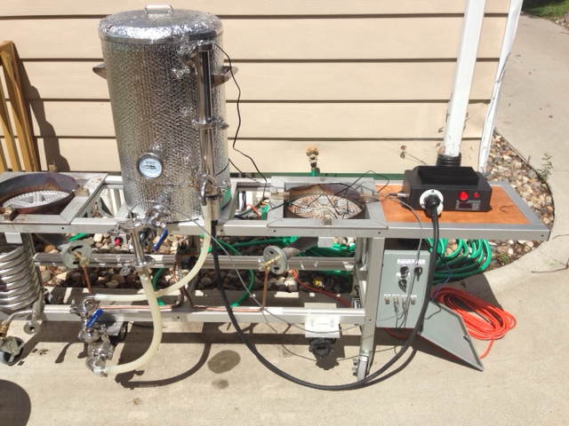
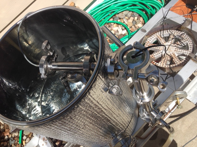
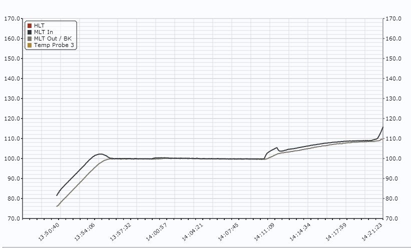
So I'm putting this firmware to the test today! I've got a RIMS tube mounted on my MLT and I'm cycling water. I've got a BCS setup to measure temp at the inlet & outlet of the MLT (see pics).

Constant Output mode works well / reliably. Constant Temp mode does not seem to work consistently, I started with 70 degree water and set a setpoint at 120; the controller raised the temp to 100 and stopped. I then raised the setpoint to 140 and nothing changed. I then used CO mode to push the temp above 100 (to 106) and then switched back to Ct mode (setpoint at 140) and it raised the temp up to 110 and held (not to 140). Then I bumped the setpoint up to 150 and it heated up correctly to 150!

I also played around with the Proportional & Integral gain; this just impacted the speed of temp change, not the accuracy of the apparent setpoint.

Any thoughts? Anything you'd like me to test / try? Is there a setting I'm missing?

It's not perfect yet, but this is gonna be really cool when we get it working!

photo 1.JPG


photo 2.JPG


Trace.JPG
 
Hi Will!
Thanks for testing and thanks for reporting! Also, nice to see some pics of your setup! Is that a prototype mashing black box?

I have had very limited opportunities to do any real testing myself. What I have done is some 'dry' testing (that is simulating). I can see a couple of things that could be problematic. One of course is that I need to review the code a bit more (well, I will need to do more of that anyway as more bugs are reported, but what I mean is that the regulator is flawed). I managed to get this working in 32 bit arithmetics, that is it compiled and the limited bench testing I've done seemed to work. SDCC has had its peculiarities before, it might well be that 32 bits isn't working out as well as I hoped, due to the compiler. It would suck if this is the case, but even so, it is doable in 16 bits, you just have to make some tradeoffs. Also, like any PI(D) parameters needs to be tuned. I don't really think this is the problem though as you tried different settings (integral clamping could also contribute here), but again this seems least likely.
I will review the code again and try some tests myself.

Cheers!
//mats
 
Hi from Norway Alpha.
Great job with the "+", thumbs up!
A thought, is it possible to control HLT with second probe, and use cooling, (or buzzer) as output?

Hans Einar
 
Hi!
Thanks HansEinar!
I think that it would be perfectly doable. However, I am primarily targeting RIMS/HERMS like setups. In the future, I would like it to be possible to use one probe to measure actual mash temp and one to measure output temp of the RIMS tube/HERMS coil and to allow PI setpoint to be adjusted by how far from setpoint the mash is.
If you would like that kind of setup, you are free to modify the code to your liking, it is not likely that I will incorporate it in the main firmware. Personally, I find that a stock STC (preferably a non A400_P one) is good enough to manage HLT temp and since they are so cheap, I find it easier to just use another one.
Hope you are ok with that answer.
//mats
 
Ahh.. That is better of course!
Anyway a good tip to use bad version STC's.
Got two "+" running perfect, and plan to flash this workbench PI version, and try it as soon as i get new STC`s. Is this prodject sat on hold, or are you working on it?
 
I am working on it, albeit somewhat slowly. I've been selling some units here in sweden and it has eaten away far too much of my spare time (it takes me several hours to complete a single unit with the modifications I make). I'm putting that on hold for now though (there is another guy here that has started selling STC-1000+ flashed units in his web shop).

It seems I have hit a snag with SDCC and using 32 bit variables. The version still up in the work branch does not seem to work 100%. I think I'll have to revert to 16 bits, which is a pain and unfortunately will put restrictions on the PI control. I need some time to investigate this and if that is the case revert to 16 bits.

Feel free to play around with it though, I have every intention of getting this firmware to at least a usable state even if it has been progressing slowly for a while. I really need people testing it out and reporting bugs and giving suggestions. Without feedback work will be much slower as, for one; I won't have much incentive and two; I won't be able to catch many issues by myself.

Thanks!
//mats
 
Ok, so I actually got around to do some work tonight.
I seems that 32 bit arithmetics actually do work, which is a very good thing. I don't know why the control was acting 'flaky' earlier, might be I had some implicit sign error when promoting variables for calculations (don't worry, I don't expect you to understand what that means if you are not a C coder).
It seems to work a lot better for me now anyway. And I also made some improvements towards scaling cP and cI, as well as the end result.
If this is ok, then I think I'm starting to 'get there' as far as the control algorithm goes.

Cheers!
//mats
 
That is good news! Looking foreward to test it and report back. I'm in short of STC's at the moment.
 
I have an 'unflashable' version and was wondering if your code could be modified to work with these other versions of the controller. My brother could possibly lend a hand on reverse engineering this version I have, or so he tells me. Do you think it is possible?
 
I have an 'unflashable' version and was wondering if your code could be modified to work with these other versions of the controller. My brother could possibly lend a hand on reverse engineering this version I have, or so he tells me. Do you think it is possible?

This has been raised a number of times, including by myself, and the short answer is no. The STC that is being used for these projects uses a chip that had a pre-developed (and free) programming setup that uses the arduino. The PIC/MCU's in the other 3 versions (that we know of), either don't support this programming interface, or require vendor specific tools. Any of them can be done, but require developing a (or finding an existing) programming interface first. Then the code can be ported to that PIC/MCU's 'language'.
 
This has been raised a number of times, including by myself, and the short answer is no. The STC that is being used for these projects uses a chip that had a pre-developed (and free) programming setup that uses the arduino. The PIC/MCU's in the other 3 versions (that we know of), either don't support this programming interface, or require vendor specific tools. Any of them can be done, but require developing a (or finding an existing) programming interface first. Then the code can be ported to that PIC/MCU's 'language'.

Very well put. That pretty much summarizes the situation entirely.
Just to be perfectly accurate though, there was really no pre-developed programming setup. It was more like, I didn't own a PIC programmer, and realised that the alternatives were pretty bad (in price and/or complexity). I had an idea to use an arduino (which I already owned) as an ISP programmer the same way I had done for other arduinos to change the bootloader (using the arduino as ISP sketch). I started researching the possibility and found a thread on the arduino forums of someone who had done this earlier. The code that was posted there was *hmm* how shall I put this nicely... not up to my standard. It was more proof of concept than anything. So I decided to start from scratch.
Luckily Microchip has pretty good documentation, even describing the upload process, making this at all possible.

The PIC is (or at least was) popular in DIY electronics, and free tools are available.
These other versions use very much more obscure MCU's. The limited documentation that can be found is in chinese and free tools are lacking.
In my regular job (in IT) we often draw the comparison between building a system to building a house (need a strong foundation and so on). If I were to make the same comparison here, it would be like trying to build a house without plans (documentation) and tools (well... tools). It is hard enough with the 'correct' prerequisites. It would be almost impossible without.
You would probably need to actually buy the tools for the specific vendor and need to reverse engineer the process of uploading as well (which may or may not be legal, I don't know). You are looking at an immense amount of work for even an experienced hacker and would probably have to drop some serious cash to buy the tools. Neither of which I am willing to do.
To me this is obvious, but I understand that 'from the outside' it could appear like a small thing to simply 'port the code' and be done. It isn't anything like that. It wouldn't even be like starting over, you'd be starting over at negative 'a lot'.

Wow, I guess I didn't really feel like doing any actual work tonight after all :)
If you got all the way here, then my apologies if I bored you :)

Cheers!
 
I am not even going to pretend to understand, but I think I get your overall meaning. I just happened to be reading the posts here when he walked in and looked over my shoulder and asked what I was working on. I told him and he seemed interested. Said he had reverse engineered some sort of hardware in the past and found it "fun". He is a pretty smart guy and was designing and building some pretty impressive circuits when he was in early high school back in the 70's so I figured he knew what he was getting into here. I will let him know what you said about it. I appreciate your response and also all the hard work you put into these projects here.
Cheers,
Kerry
 
Very well put. That pretty much summarizes the situation entirely.
Just to be perfectly accurate though, there was really no pre-developed programming setup. It was more like, I didn't own a PIC programmer, and realised that the alternatives were pretty bad (in price and/or complexity). I had an idea to use an arduino (which I already owned) as an ISP programmer the same way I had done for other arduinos to change the bootloader (using the arduino as ISP sketch). I started researching the possibility and found a thread on the arduino forums of someone who had done this earlier. The code that was posted there was *hmm* how shall I put this nicely... not up to my standard. It was more proof of concept than anything. So I decided to start from scratch.
Luckily Microchip has pretty good documentation, even describing the upload process, making this at all possible.

Ah, I thought you pulled it together for the STC, but clearly you put a lot of work into the PIC programming side as well. My apologies for selling you short! Great work!
 
I currently use a r.i.m.s system with manual controls. As far as features that I can think of, I have never needed more than 4 profiles. That includes the sac rest. I like the idea of using the on-board beeper for notifications when the steps are done. IDK if you could so a single beep at the end of the first step, a double beep at the end of second, and so on. With a long beep at end of final step. Or something like that anyway. If not, single beeps would be great as well. Also, as far as using the second relay for a pump control kind of scares me for some reason. On my system I don't have anything to notify me of a stuck mash so I have to monitor flow manually. I like to have my pump switch available to me for quick shut-off I guess.
 
Ah, I thought you pulled it together for the STC, but clearly you put a lot of work into the PIC programming side as well. My apologies for selling you short! Great work!

No worries :) It was a bit of work, but having good documentation made not all that hard. Writing the firmware has been a lot more work in comparison.

I currently use a r.i.m.s system with manual controls. As far as features that I can think of, I have never needed more than 4 profiles. That includes the sac rest. I like the idea of using the on-board beeper for notifications when the steps are done. IDK if you could so a single beep at the end of the first step, a double beep at the end of second, and so on. With a long beep at end of final step. Or something like that anyway. If not, single beeps would be great as well. Also, as far as using the second relay for a pump control kind of scares me for some reason. On my system I don't have anything to notify me of a stuck mash so I have to monitor flow manually. I like to have my pump switch available to me for quick shut-off I guess.

Thanks a lot for the input! I'll probably drop a profile to make room for more settings. A beep at the end of the step seems like it could be possible to implement, but I'm considering just using the buzzer to indicate the program is finished (that way the signal could be used to control a solenoid valve as well), if there is space left, maybe it could be configurable. I have some features I really want to add first though.
About the pump switch, yes, I intend to have manual override switch myself. But I like the idea of having it automatic as well.
 
is the turn-on voltage for those on-board relays compatible with an SSR? I have a couple on the shelf here and one is 3-32v, and the other is 3.5-15v. If not, would we be safe grabbing the positive dc pin on the on-board rectifier bridge and use that through the existing on-board relay outputs?
 
is the turn-on voltage for those on-board relays compatible with an SSR? I have a couple on the shelf here and one is 3-32v, and the other is 3.5-15v. If not, would we be safe grabbing the positive dc pin on the on-board rectifier bridge and use that through the existing on-board relay outputs?


Yes it is. It uses 12v (ish... It will probably be more like 14v due to not being regulated) to drive the relays, see link in post #5 in this thread to another thread on how to modify the STC for SSR output.
If you do, make sure to label the STC correctly, so no one will accidentaly hook up mains voltage to the output again.
 
As the STC-1000 only has one temperature probe, I intend to use one unit for HLT temperature control and another unit to control the pump which will in turn control the mash temp. I figure these things are so damn cheap, why even worry about trying to control both with one unit.

I have a really cool idea, but don't know if it'll work. So... before I mention it, does the STC-1000 have any way to determine if current is flowing through the relays? I know it is smart enough to determine if the probe is connected or not but my idea requires it to be smart enough to know if current is flowing through the relays.
 
Who said the STC only has one probe? I challenge that :)
And no, it can't know if current is flowing through the relay. It doesn't 'know' the temp sensor is not connected either, it only know the value it reads is out of range of expected input.
 
Back
Top