• Please visit and share your knowledge at our sister communities:
  • If you have not, please join our official Homebrewing Facebook Group!

    Homebrewing Facebook Group

How To: BrewPi LCD Add-On

Homebrew Talk

Help Support Homebrew Talk:

This site may earn a commission from merchant affiliate links, including eBay, Amazon, and others.
I'd happily do the work, but gonna take me a while. Not that I'm ridiculously busy, but have ZERO electrical or engineering skills, and have never even attempted anything like this before. (Just downloaded Eagle and am scratching my head, haha). That said, beer is the great equalizer, so surely know SOMEONE locally who can do this, that can be bribed by a certain amount of beverage.

That aside, wouldn't want to step on Elco's toes, or take bread off his table with his current projects. But since he's no longer offering Arduino items for sale, would assume that getting a dozen or two PCBs made that would be distributed via a group buy to folks who'd be DIYing shields anyways wouldn't be an issue?
 
I can see why Elco doesn't want to give away the eagle files though, as no one would be the spark if they knew they could get a basic brewpi for less than $5.

Yep. Definitely can't blame him - he's put a lot of work into developing this, and he's ended up doing something we all dream about, earning a living doing something he loves. (And chances are it's not much of a living, am sure this doesn't let him give up his day job.)

BUT, the RevC schematic was given out freely (although not any more), which is what day_trippr based this DIY shield on. While I think just copying Elco's work is offside, converting the shield into something that means DIYers don't have to dribble solder all over (and remember, everyone would still have to buy the various components and Pi/Arduino - unless you have most of those lying around, you quickly get to the cost of a new BrewSpark) doesn't really mess with things?
 
Really the only thing you "need" the shield for is the lcd and rotary encoder. Everything else is basically plug and play.
 
Really the only thing you "need" the shield for is the lcd and rotary encoder. Everything else is basically plug and play.

True. But... the lcd just looks so NICE, hahaha. And while for many folks, not having it isn't an issue, speaking for myself my fermentor is in the garage, so it's nice to be able to glance at the screen in passing to get a status update, rather than constantly check via a web browser. And think if it were easier to implement, more folks would do it. I've got SOME soldering experience, and I know I for one look at the instructions with a fair amount of nervousness.

An unpopulated shield would sort of the sweet spot between complete DIY and buying a premade kit off the shelf.
 
When I'm finally done if I do have an lcd it's going to be on a mobile minion setup. Right now my plan is to have a single 15" screen that displays all my fermenters lcds on one screen.
 
I'd happily do the work, but gonna take me a while. Not that I'm ridiculously busy, but have ZERO electrical or engineering skills, and have never even attempted anything like this before. (Just downloaded Eagle and am scratching my head, haha)...

If you are going to be learning a new bit of software anyhow, I would recommend starting off in KiCAD. It's not the industry standard, but offers a few things that are a positive for us hobbyists.

1. It's open source (and Free)
2. It does not have any restrictions on board size or quantity of copper layers (Like the Free version of Eagle does)

It is a bit more cumbersome to learn than Eagle. But once you get the flow of operations down, it actually makes a bit more sense.
 
Wow. If it's more cumbersome than Eagle, I'm screwed. I just downloaded the PCB layout of the protoshield, figuring it wouldn't be that hard to just modify that using day's layout on page 2, but it's about as intuitive as a self operating napkin. That said, I'm used to Photoshop and Illustrator, so just assumed drawing lines would be... drawing lines.

Looks like I'll be butchering a protoshield after all!
 
Nice spot, bigdaddy - those, alas are the first revision boards, which (apparently?) had some issues. Think RevC is the current (last) one, and the one most recommended.

That said, my nefarious plan is to con day_tripr into doing it when he gets back from the tropics... a shield with his little modifications to it to allow for the serial/bluetooth and switches would be lurvely! ;)
 
Anyone who knows what they're doing wanna check my horrifically shoddy work? Been on this damn thing for five hours, and think I'm done with the shield - but too tired to hook it all up to the encoder and whatnot yet.

front.jpg


arse.jpg
 
Got everything up and running. doing some testing right now all that seems to be going go. Just wanted to see if one of you could tell me the best way to wire up a couple of PC fans. I'd like for them to run all the time to keep the air moving is there a way to do it to run off the relay or the plug? Or wire them together and add plug
 
If they are going to run continuously. Then get a wall wart rated for the voltage you need. Some pc fans run off 5v some off 12v. Then just wire them up to that and plug it in.
 
Well, smack my arse and call me Shirley.This is promising at least...


Weeeeell, spoke too soon. Getting nothing from my temp probes on the onewire, and the rotary encoder's doing diddly squat. Aaaaand, I can't get the wifi working on the Pi. Aaaaand now I can't reprogram the Arduino... Grrr....

IMAG0179~2.jpg
 
Have a look at post 81 re the board not being able to be programmed when I made mine i initially got a message saying it was an incompatible arduino. If the temp probes show up but don't show a value, check the soldering between the live and data and that you've not double up on resistors between the top.cant help with the rotary encoder as I never got that far.

The wifi on the pi sounds like it's the pi to me.

Still waiting on an arduino and protoshield to arrive from China I have a feeling they've been lost in transit.
 
The temp probes aren't showing up at all with the shield, which had me checking the soldering, but can't find an issue. Took the shield off, same problem. So for the 60th time, pulled the SD card, wiped it, and started again. Now, the probes show up (without the shield, have reverted to the most basic version to at least get it part way working) but BrewPi won't save them in the components area, hitting refresh just shows them back to being unassigned (they are showing temp). Per Elco, this is an EEPROM issue, so ran ICE and zeroed the EEPROM out, which meant I had to reflash the hex file, which brought up even more issues with errors about this, that, and the other.
 
Since you are able to recreate the problem every time you wipe the system and start over. It tells me that either you are missing something critical everytime or something is wrong with either your arduino or the hex file you downloaded. That being said, it's kinda hard to fix the problem if you completely start over every time without actually finding what the problem is first. Have you tried typing "echo -ne 'E\n' > /dev/ttyACM0" into terminal before trying to upload the hex file again? Without the quotations...
 
As mentioned, at this point I'm not using the shield, having gone back to the barebones "make a cheap brewpi for under $100" configuration of just the Uno, Pi, relay board, and handful of jumper cables (and the sensors). So issues with the shield (and am sure there are some!) are on the shelf for now.

The overwhelming issue is BrewPi writing to the Arduino. First time - before the shield - I tried this, and everything seemed to work without issue once I realized the Pi wasn't installing (or coming with) the Arduino core during the "standard" install. Once I got that in there, I got it up and running, did my happy dance, and shut everything down. When I fired it up again the following day, I noticed the Arduino hadn't saved the configuration, so tried to save it again, and it wouldn't take. At this point I've gone through 6-7 USB cables (since "cheap" cables seem to be an issue, but now am using a brand new gold plated one, and same issue!), I've assumed the hex file was corrupted so redownloaded that, but no deal. Every time I try to reprogram the Arduino via the maintenance panel, I get an error - rarely the same one. The constant wiping is generally the end result of threads I see on the brewpi forum, where the "well nothing else has worked, so try resetting the Arduino with the base sketch, wiping the EEPROM, and uploading a new hex file"

(Just noticed in the main thread that someone had the same issue, and mentioned there's a bug in the code that requires manual downloading of some files, so will try that later on.)

I suppose at this point, I do need to be looking at the Arduino itself (it's a genuine one, not a clone), and wondering if something's fakakta in there. I did try a Leonardo as well, but no dice there either. (That said, the Leonardo's been through the wars, so...)
 
Because that's what fixed the devices not getting installed for many a user

Oh, you magnificent bastard! I owe you a pint. Sensors and whatnot are now stored. Hopefully they'll survive a reset this time! Now onto the shield...
 
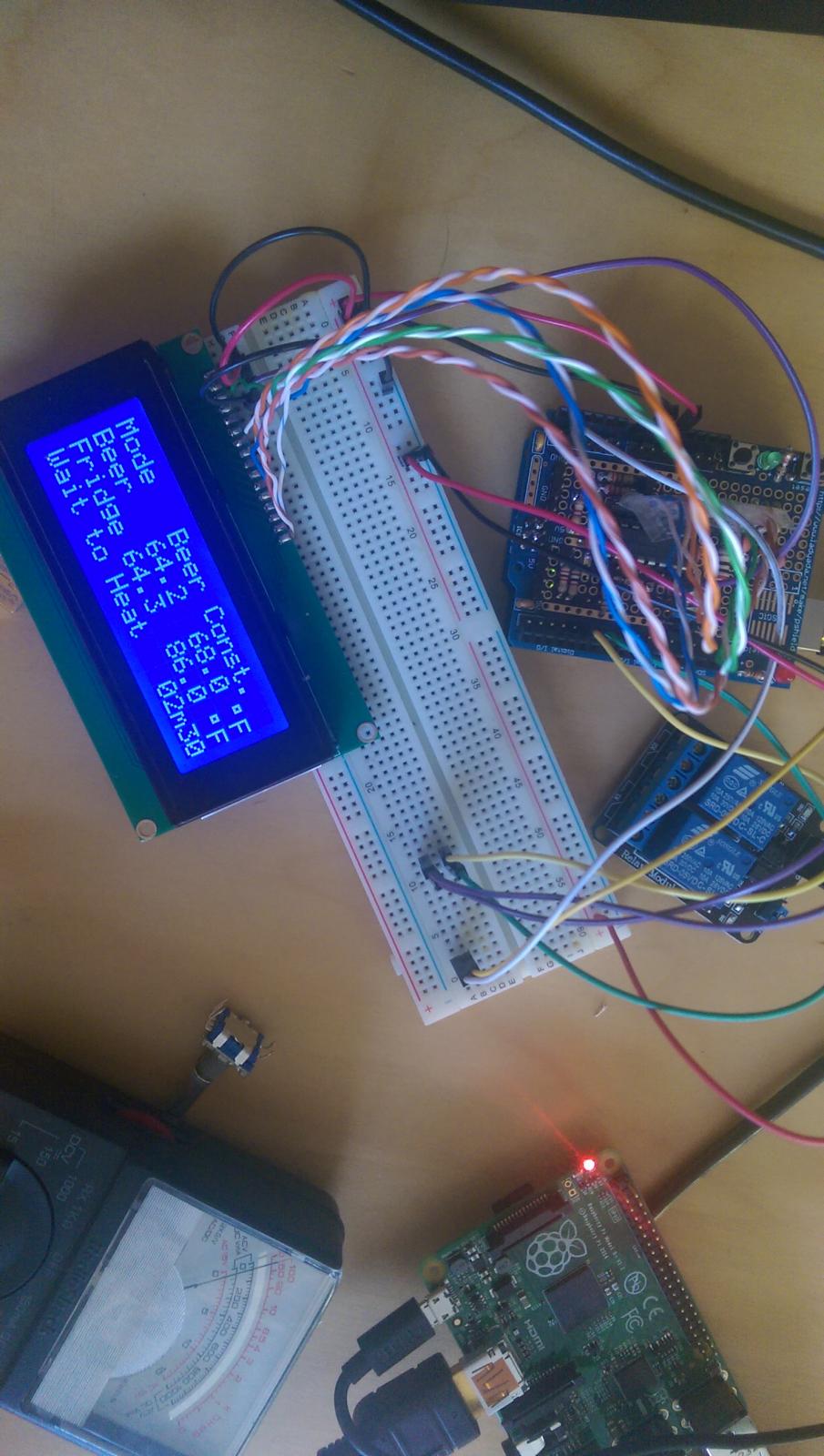
Okay, so the Arduino itself seems happy now. In it's shieldless configuration, everything seems to be working away. Hooray!

When the shield is added though, it's not seeing the onewire goodies at all. Sees the digital pins (heater cooler action) without issue, but it won't show the thermoprobes under devices. Nor is it showing any of their data in the LCD screen. This is confusing me, since for all of the wiring and shenanigans going on with the shield, the onewire is just a resistor connected to the 5v rail, then jumped onto the shield's analog pin 4, right? The simplest thing in all of it? Checked my work there, and don't see any issue - pulled out the multimeter, and not seeing any issue either. Anyone got any thoughts on that?
 
Well, weird. I went over the connections again with the multimeter, this time checking for voltage to make sure there was power getting to that rail. Had a weird needle spike when I measured, almost like the capacitor needed to discharge, and now... and now...

Think it's just the !@#$@# rotary encoder now!

IMAG0192.jpg
 
Oof, rotary encoder is a pain in the buttocks! I assume centre pin of the three to common, and one f the two switch pins there too?
 
Ubermick have you just edited your post? I don't think the rotary encoder attaches to the 10k pot the three wires attach to the capacitors and resistors to the left of the shift register I think. Those are attached to the ground rail, see the diagrams on page 2 I think.
 
Ubermick have you just edited your post? I don't think the rotary encoder attaches to the 10k pot the three wires attach to the capacitors and resistors to the left of the shift register I think. Those are attached to the ground rail, see the diagrams on page 2 I think.

Yep, I spoke before I thought. Or rather, I posted before I Googled. Based on the wiring diagram on page 2, and having never worked with rotary encoders before, I assumed pins 7, 8, 9 ran to the bottom three pins on the encoder, with the top two unused. Which I tried, and not surprisingly, didn't work. Then I googled a wiring diagram, and read that only one of the pins (either switch side or rotary side) need to be grounded. Turns out the way I have it, both the centre pin of the rotary side, and one of the pins on the switch side need to be grounded (so five wires running from the Arduino instead of three in the diagram). Of course, I'll pull out the soldering iron and jump the two grounds together meaning just four. But still more than the three I assumed. (and we all know what happens when I assume, haha).

But... drumroll... it's all working now! I got the wifi finally (FINALLY!) working on the Pi, the Arduino is now magically (no CLUE why this changed) remembering settings, the display is working, the rotary encoder is working... so all I need to do is make some nicer jumper wires from some ribbon cable, plop this in an enclosure, and I should be good to go.

Big thanks to everyone for their help! (But still think we should put together a board and do a group buy!)
 
I'm down if we can get day_tripper to design it with all his free time...
 

Latest posts

Back
Top