• Please visit and share your knowledge at our sister communities:
  • If you have not, please join our official Homebrewing Facebook Group!

    Homebrewing Facebook Group

HOWTO - Make a BrewPi Fermentation Controller For Cheap

Homebrew Talk

Help Support Homebrew Talk:

This site may earn a commission from merchant affiliate links, including eBay, Amazon, and others.
Status
Not open for further replies.
My probes are on 1m wires. I say em interference because every since I brought this fridge home I've had problems with wifi devices all over my house.

Ok, that would definitely drive me insane. I feel your angst ;)

Also while I'm testing there at high and low voltage wires going every which a way.

Do you have your BrewPi system sitting in the middle of all that?

Cheers!
 
ImageUploadedByHome Brew1406242679.925374.jpg
 
I wish I could get a preassembled revc board for less than 68 bucks. I can buy 4 arduinos for that price or 2 pi's.
 
Your setup doesnt look any better or worse than mine did, although i will say using alligator clips probably isnt the best idea in terms of high voltage and supplying power.
 
I put shrink tubing on the handle part!

Alligator clips are meant for debugging and prototyping, not functional circuits.

Atleast that's my take, i would replace those with wire twist caps or screw the wire down to the actual socket...i see another alligator clip running to your socket which seems super sketchy to me.
 
The clips are only going to my ferm wrap. It draws half an amp nominal and only runs like twice a day
 
Hey I built my entire brewery with those test leads. They are super legit.

Your also the only person here out of 20+ that have built it with this problem and the only one using them :mug:

Im not saying thats the issue, but its the only thing i can see thats different than everyone elses setup.

Good point about the EMI from the relay shield though trippr, thats definately a possibility.
 
This is all just testing at this point anyway. My intention is to build 2 carboy sized chambers inside the fridge. And use fans and ducting to draw cold air from the top to cool independently. Using 2 separate arduinos. Then a third arduino to control the freezer as a lagering crashing chamber for my secondaries. I wish it was practical to use the 4 relay shield that I have now but brewpi just wasn't written to use its pinout. I'll probably end up building it into the fridge to control 4 ferm wraps and just remote the pins to the 3 arduinos.
 
Your also the only person here out of 20+ that have built it with this problem and the only one using them :mug:


Im not saying thats the issue, but its the only thing i can see thats different than everyone elses setup.


I'm beginning to think there is an issue with my pi. I'm re-everythinging all my software on it. Since I've been messing around with the kernel and stuff. I'll get everything back up and running fresh and see if it goes away.
 
Problem solved. BrewPi Uno#2 with the three probes sits right where I set my beer and the power lead to the One-Wire breakout board wasn't making the best connection to the Uno's socket. If even I looked at it sideways the 5V to the probes would drop out. Scrubbed the pin in and out of the Uno socket and now I can do the drum solo from In A Gadda Da Vida without perturbing BrewPi...

So...what to do next while waiting for R'Pints v.2...

Cheers! ;)
 
Ok wish me luck I'm running the 12 day sample profile. Let's see how she does.
 
Anybody got an old kenmoore fridge laying around that has a good fan motor in it?
 
There really isn't much heat dissipated by the 'Pi, Arduino and relay board, and all of the components have at least a commercial rating (so they're good way above the temperatures you'll see in a garage - even one that's too hot to spend any time therein).

I'd be more concerned with the freezer compressor than any of this stuff...

Cheers!

I'm always concerned about the freezer compressors. I used to have 5 of them in my garage. I've had two go out on me at different times, but close together in time. It is a pain in the arse to move things around to consolidate. I only have 4 in there now.:drunk:
 
Hello all. Thanks for this great thread.

I'm trying to get the BrewPi up and running with a physical LCD display, but have no real output showing. The LCD powers on and shows two rows of blocks. The POT works to adjust contrast. But no characters as emulated in the top left hand corner of the BrewPi interface.

Do I need to modify any code in BrewPi to enable the display or will it work out of the box?

Thanks in advance for any suggestions!

======================
Background Info
======================

I am using a 20X4 board compatible with the Hitachi HD44780 driver, with 16 pins.

I have wired the LCD according to the following:

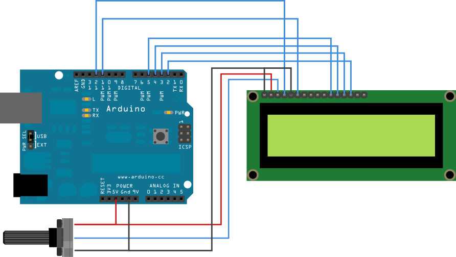
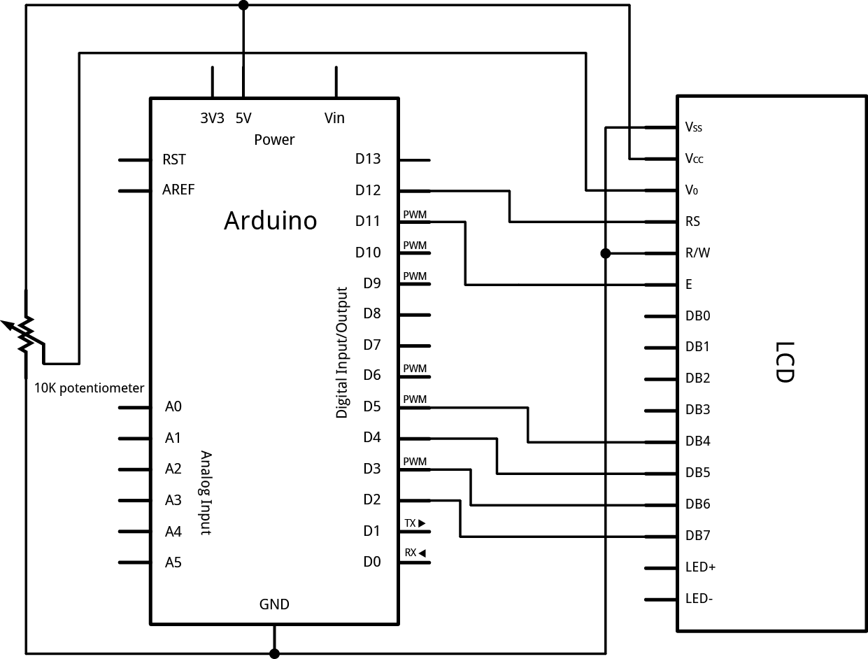
Wire your LCD screen to your Arduino. Connect the following pins:
LCD RS pin to digital pin 12
LCD Enable pin to digital pin 11
LCD D4 pin to digital pin 5
LCD D5 pin to digital pin 4
LCD D6 pin to digital pin 3
LCD D7 pin to digital pin 2
Additionally, wire a 10K pot to +5V and GND, with it's wiper (output) to LCD screen's VO pin (pin3).

LCD_bb.png


LCD_schem.png

This is the schematic you want. You'll need a 595 shift register. No reprogramming of pins. Should be able to wire it up and have it work. I'm leaving on vacation for two weeks tomorrow or I'd throw this together and test it out. If nobody has by the time I get back maybe I'll put it together.

LCD_using_74HC595_and_SPI.png
 
Hey MongooseMan. Have you tried say a minute of video every hour?


Sent from my iPhone using Home Brew

I tried my hand at setting up a VLC stream yesterday.
That worked fine (I could view the stream using VLC on my laptop), but is tricky to get into a webpage, which is my priority.

I did increase the number of photos per minute (just by adding lines like this to my crontab:
"sleep 1;streamer -f..."

But I found that if you do too many, then the PC gets overloaded (it's trying take a new photo whilst still processing the old one, and hasn't fully released the device, etc) so settled on a sweet spot of 1 every 3 seconds.

The end goal is definitely a live video stream though.
Will hopefully get some time to work on that this weekend.
 
I tried my hand at setting up a VLC stream yesterday.

That worked fine (I could view the stream using VLC on my laptop), but is tricky to get into a webpage, which is my priority.


I did increase the number of photos per minute (just by adding lines like this to my crontab:

"sleep 1;streamer -f..."


But I found that if you do too many, then the PC gets overloaded (it's trying take a new photo whilst still processing the old one, and hasn't fully released the device, etc) so settled on a sweet spot of 1 every 3 seconds.


The end goal is definitely a live video stream though.

Will hopefully get some time to work on that this weekend.


How about using some HTML5 video.
 
OK, here's a quick tut on how to get live video streaming onto your brewpi page (following on from this post on getting images from your webcam onto the page):

Disclaimers:
  • I've tested this in chrome, it works there
  • I've tested this on Safari on iOS devices, it does NOT work there
  • I've tested this using VLC on iOS devices, it works there

Setting Up VLC:
(Get VLC if you don't have it-> sudo apt-get install vlc)

Make sure your user has permissions to access the webcam:
Give a group called 'video' ownership of the webcam:
Code:
sudo chown root.video /dev/video*
Then, add 'brewpi' to the group:
Code:
sudo adduser brewpi video
Then, give brewpi access:
Code:
sudo chmod g+rw /dev/video0
That should work great. (Source)

Create a file in your home folder called "webcam.sh"
In it, put the following:
Code:
#!/bin/bash
cvlc v4l2:///dev/video0 :v4l2-standard= :input-slave=oss://denull :live-caching=300 :sout='#duplicate{dst="transcode{vcodec=theo,vb=1024,channels=1,ab=128,samplerate=44100,width=320}:http{dst=:8084/stream.ogg}"}'
Note: If your video still doesn't work because of permission errors accessing /dev/video0, then you can add the following line to your shell script, above the cvlc line (replacing the <password> bit with your brewpi password):
Code:
echo <brewpi password here> | sudo -S chmod 666 /dev/video0
Obviously, echo-ing the password into the sudo is bad and should be avoided if you can.


Save that file.
You can test it by running it (./webcam.sh) over SSH and seeing if VLC on any other computer can get to the stream (File->Open Network Stream->http://<brewpi address>:8084/stream.ogg

Making the script run on startup:
Now you want this script to run every time the computer starts up, so we'll add a task to the crontab:
Code:
crontab -e
Add a line at the bottom like so:
Code:
@reboot /home/brewpi/webcam.sh > /home/brewpi/vlclog.log 2>&1 &
This tells cron to run the script on reboot, and to pipe the output to that log file, just in case.

Adding the video to your page:
Now that that's working (hopefully), you can edit your index.php file to include the video:
So, where we previously had the canvas (down at the bottom of the page), we'll now just have this simple code:
(again, replacing the url portion with the correct address)
Code:
<video id='webcamVid' width='600px' controls>
[INDENT]<source src='http://<brewpi url>:8084/stream.ogg' type='video/ogg'>[/INDENT]
</video>

Reload the page in Chrome, and you should see the live stream from your webcam.
Good luck, let me know how it goes!

webcampi.jpg
 
Hey everyone, I've been trying to get this setup for the past few days.

I've got the BrewPi page up and running. It lets me access the maintenance panel and it seems every other feature is running fine.

I just can't seem to get my temp sensors recognized. I wired one DS18B20 sensor just like FuzzeWuzze's example on the first page, and it didn't recognize it. So I wired both just like he posted, and still nothing. The only difference is that I don't yet have the relay board wired, but I didn't think that mattered.

Any suggestions? I've followed all the instructions on here and the BrewPi documentation for configuring a device. Ground goes to GND, VCC goes to 5V (tested it with voltmeter just in case), Data goes to A4, and 4.7k ohms resistance between the VCC and Data. What's wrong?
 
At least I know how to find the ground pin now using a tester. For everyone else. Set to ohms 2k. With 1 lead on com and the other on V-ohm. Start testing by taking 2 wires and placing one of each on a separate tester leg. When you get a reading look at your leads. The one attached to Vohm is your ground. Now keep that one attached to ground alternating the other 2 wires to read their values. The higher value is you 5v in and the lower value is data.


I posted this earlier when I found out how to figure out which wire goes where
 
I posted this earlier when I found out how to figure out which wire goes where

I actually found your posts by searching the thread right after posting my question! I almost sent you a pm asking which one you have. I'm pretty sure we have the same one because mine also have the red, yellow and green wires. Who would put green for anything but ground?! That's so weird.

I've very hopeful that this will solve me problem and then I'll start working on the relay and outlet circuitry. I'm not able to see if this is the solution until later. I really do hope that's it.
 
Status
Not open for further replies.

Latest posts

Back
Top