Question about GFCI

Homebrew Talk - Beer, Wine, Mead, & Cider Brewing Discussion Forum

Help Support Homebrew Talk - Beer, Wine, Mead, & Cider Brewing Discussion Forum:

This site may earn a commission from merchant affiliate links, including eBay, Amazon, and others.

Spartan1979

Supporting Member
HBT Supporter
Joined
Feb 13, 2011
Messages
2,258
Reaction score
789
Location
O'Fallon, MO
I'm working on my electric brewery and a buddy is helping with the panel. His uses a Raspberry Pi as a controller but he's only using a three wire plug.

Anyhow, I know if you're using a 4 wire plug you can run a pump off one of the two 120 volt legs. He's under the impression that this will trip the GFCI. He thinks that the GFCI is measuring the difference between the two hot legs and if they are different, it will trip. Since I know most panels are also controlling pumps I knowthis can't be correct. Can someone explain how this works so I can tell him?

Thanks.
 
I'm running a 4-wire panel and run the pump and element at the same time, and it's not tripping my GFCI breaker.

I believe (not certain) that the GFCI is comparing something with the ground wire. Difference between the legs doesn't enter into it.
 
A 240V GFCI monitors the current on the two hot legs AND the neutral wire. If there is an imbalance between all three, then the GFCI trips, but not if there is an imbalance between the hot legs.

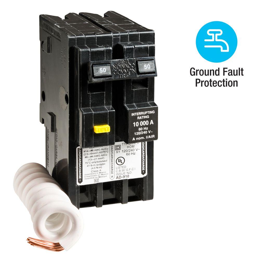
See the picture below: The two hot wires to the load go onto the outer two terminals at the bottom. The neutral wire from the load connects to the terminal in the middle (always follow the wiring instructions - the terminals might not match up if the breaker manufacturer is different than the one shown). This way, the entire circuit is passing through the breaker; if it senses an imbalance between what's going out vs. what's coming back in, then it must be flowing through the ground and it trips. The white wire on the breaker connects to the neutral bus bar to tie the neutral to zero potential.

square-d-2-pole-breakers-hom250gficp-64_1000.jpg
 
Last edited:
Thanks for the response. I'm trying to understand how these things are wired to I can feel safe and comfortable using it. I was looking at this diagram for wiring an Auber Cube. Since the heater outlet is wired with two hots and a ground, wouldn't that cause an imbalance between the neutral and the two hots tripping the GFCI?

Also, wouldn't the element be getting 110V all the time assuming the breaker switch is on?

9rgPAzj
 

Attachments

  • cube.PNG
    cube.PNG
    135.3 KB · Views: 92
Thanks for the response. I'm trying to understand how these things are wired to I can feel safe and comfortable using it. I was looking at this diagram for wiring an Auber Cube. Since the heater outlet is wired with two hots and a ground, wouldn't that cause an imbalance between the neutral and the two hots tripping the GFCI?

Also, wouldn't the element be getting 110V all the time assuming the breaker switch is on?

9rgPAzj

Ok, this is going to take a bit of an explanation of how AC current works is a split-phase setup like US homes have. If you live somewhere other than the US, then it might be different. You need to understand that AC current cycles between +120V and -120V 60 times per second.

AC service to your house is set up with two 120V supplies (the black and red wires). These two supplies are 180 degrees out of phase from each other. This means that when the black supply is at +120V, the red is at -120V. When you measure the voltage difference between these two, you get 240V (+120V -(-120V)). For either the black or the red wire, if you measure the voltage from "hot" (red or black) to neutral (white), you get 120V no matter which one of the "hot" wires you chose, because the neutral is always at zero potential.

When you only have a 240V heating element wired up to the red and black wires, all the current is flowing through those two wires, and nothing goes through the neutral (white) wire or ground (green or bare copper).

When you have a 120V load like a pump wired up between the black and white wires, you get current flowing through the black and white wires.

Let's throw some numbers into this for clarity. Assume one 240V 5500W heating element and one 120V pump:

The heating element is 5500W at 240V; that's 22.9 amps (P=V*I) flowing from black to red
Let's assume the 120V pump is pulling 2 amps from black to white.

That means the black wire is carrying 22.9 + 2 = 24.9 amps
The red wire is carrying 22.9 amps
The white wire is carrying 2 amps

Now, the GFCI breaker is using a current sensing ring that has all three (black, red, and white) wires inside it. The total current going in (24.9 amps in the black wire) exactly equals the current going out (22.9 amps in red + 2 amps in white), so there is NO imbalance across the whole circuit.

If you have a ground fault on the black wire for example, then some of that current going out through the black wire is not coming back through the red and white wires; it's flowing through the ground wire (and potentially through YOU on the way...). Since it's going through the ground, it's NOT coming back through either the red or white wires. The current sensing ring only measures through the black, red, and white wires. Now the current going in doesn't match the current going out. That IS an imbalance and will trip the GFCI.

I hope that helps. This stuff can be fairly tricky to understand when you are working with a split phase system. Here's a good reference: https://en.wikipedia.org/wiki/Split-phase_electric_power Figure 1 shows how US household service is set up.
 
Last edited:
As I think about this (and I have a tendency to overthink things) I figured out why, in the graphic I attached, why there wouldn't be 110v always running to the element. Since it flows from black to red, if you switch off one, the circuit is open and no electricity can flow.

Also, technically, and I would never suggest doing this, the element plug doesn't even need a ground wire to function. It has to be there for safety, but it would work without it. Correct?

Well, yes it would technically work without it, the ground is needed for safety. It gives electricity a path to follow in case something goes wrong. Don’t ever skip the ground or it might take you as the path of least resistance! Remember that even UL listed equipment has a grounded plug; we’re dealing with home made jury rigged stuff here - the chances of something going wrong is much higher than something designed and built to UL specs.

Also, switching only one of the hot legs (black or red) will shut off the circuit, but you still have one of the hot wires physically connected to the load. If something goes wrong here, you can still have a short because one of the wires still has 120v potential on it. It’s best to switch both hot legs off to eliminate that risk. A double pole switch or contactor will do that. Make sure whatever you use to shut off the circuit is rated for the current in that circuit. For a 5500w heating element, you’ll want at least a 30 amp rating.
 
Last edited:
Hey Wiz.... GREAT explanation on how GFCI works in split phase.

Chris

Thanks! When I first started down the path of electric brewing, I made sure I fully understood what I was doing. Water and electricity don’t mix very well, and I was not going to risk my life - beer is important, but not that important!
 
Well, yes it would technically work without it, the ground is needed for safety. It gives electricity a path to follow in case something goes wrong. Don’t ever skip the ground or it might take you as the path of least resistance! Remember that even UL listed equipment has a grounded plug; we’re dealing with home made jury rigged stuff here - the chances of something going wrong is much higher than something designed and built to UL specs.

Also, switching only one of the hot legs (black or red) will shut off the circuit, but you still have one of the hot wires physically connected to the load. If something goes wrong here, you can still have a short because one of the wires still has 120v potential on it. It’s best to switch both hot legs off to eliminate that risk. A double pole switch or contactor will do that. Make sure whatever you use to shut off the circuit is rated for the current in that circuit. For a 5500w heating element, you’ll want at least a 30 amp rating.

I will definitely have a ground. I was just asking that question to make sure I understood how things work.
 
...

Also, wouldn't the element be getting 110V all the time assuming the breaker switch is on?
Yes, whenever the breaker/main power switch is on, the element will be energized @ 120V relative to ground. If you measured the voltage between the two AC terminals of the SSR with the SSR off, you would measure 240V. Also, if you unplugged the element, and measured between the two hot terminals in the element outlet, you would also measure 240V when the SSR is off. This second effect is because the SSR is not a perfect switch, and allows some current leakage even when it is off. This is also why you want to have a mechanical disconnect on your power feed so that you can remove all voltage when desired.

Brew on :mug:
 
As I think about this (and I have a tendency to overthink things) I figured out why, in the graphic I attached, why there wouldn't be 110v always running to the element. Since it flows from black to red, if you switch off one, the circuit is open and no electricity can flow.

Also, technically, and I would never suggest doing this, the element plug doesn't even need a ground wire to function. It has to be there for safety, but it would work without it. Correct?

What Wiz said. Switch em both off cause there's still 120V that can come out and play if you touch the wrong thing. And grounds are never optional. Ever.....

Cheers!

Chris
 
I will definitely have a ground. I was just asking that question to make sure I understood how things work.

What Wiz said. Switch em both off cause there's still 120V that can come out and play if you touch the wrong thing. And grounds are never optional. Ever.....

Yup. In a perfectly-functioning system, the ground will never be used to carry current. Everything will operate as expected with just two conductors--Hot/Neutral for 120V, Hot/Hot for 240V.

The reason we have grounds is for the rare cases when something isn't functioning perfectly, because the potential consequences of not having it in those cases includes undesirable side-effects like death.
 

Latest posts

Back
Top