On/off switch - necessary?

Homebrew Talk - Beer, Wine, Mead, & Cider Brewing Discussion Forum

Help Support Homebrew Talk - Beer, Wine, Mead, & Cider Brewing Discussion Forum:

This site may earn a commission from merchant affiliate links, including eBay, Amazon, and others.

thelawlost

Member
Joined
Apr 20, 2011
Messages
13
Reaction score
0
Location
Minneapolis
I'm in the process of putting together a small batch e-biab system, but have a question on the control panel build. There are countless builds on here, but for the most part, I've generally seen controllers with illuminated button switches for the PID, pump, and element, and an E-stop button, but no on/off switch. But with the illuminated buttons, if you don't have power to the panel (as in, before you have plugged it in), you can't tell if the switches are in the "on" position, right? I personally dislike the idea of plugging in anything "hot", so I'd like a master on/off switch that clearly dictates whether power is going to any of the other buttons. But given the general lack of builds with such a switch, maybe I'm not understanding it correctly, and such an on/off switch is not necessary?

Here's P-J's original plan from jrb03's 20A, 2000w fantastic thread that I'd like to mirror, but with the addition of the on/off switch. Any advice is welcomed!

Auberin-wiring1-a4-2000w-BIAB-120V-D.jpg
 
The whole GFCI-tripping E-STOP is a bunch of crap. It is very dangerous to short a hot leg to ground. No engineer would EVER design a system to do that. EVER!!! And I can't believe P-J continues to proliferate that design to so many unknowing people.

To answer your original question, you can add a switch or buttons to drive a relay or contactor that switches control power (i.e. the power that drives all the relays). You can use a selector switch to drive this relay. Alternatively, a better option would be to use the E-Stop and a "Reset" button to drive this master power relay. You put the normally-closed contact of the E-Stop and the normally-open contact of the Reset button in series and put one of the contacts from the master power relay in parallel with the reset button to act as a seal-in. So you always have to push the reset button to pull in the master power relay after you lose control power. This could be after you press the E-stop or after you first plug the system in. At that point the E-Stop become the power switch (and you're not putting yourself in danger and you don't have to go reset the breaker.)

Code:
 E-STOP            Reset            Master Pwr
---]\[--------------] [----------------( )----
            |                 |
            |    Master Pwr   |
            --------] [--------

The E stop will short and trip the supply breaker. I prefer a safety controller though.
View attachment 228619

Wow. That's the first time I've seen someone with actual safety rated components in their homebrew setup. Are you using it as dual channel?
 
The whole GFCI-tripping E-STOP is a bunch of crap. It is very dangerous to short a hot leg to ground. No engineer would EVER design a system to do that. EVER!!! And I can't believe P-J continues to proliferate that design to so many unknowing people.


To answer your original question, you can add a switch or buttons to drive a relay or contactor that switches control power (i.e. the power that drives all the relays). You can use a selector switch to drive this relay. Alternatively, a better option would be to use the E-Stop and a "Reset" button to drive this master power relay. You put the normally-closed contact of the E-Stop and the normally-open contact of the Reset button in series and put one of the contacts from the master power relay in parallel with the reset button to act as a seal-in. So you always have to push the reset button to pull in the master power relay after you lose control power. This could be after you press the E-stop or after you first plug the system in. At that point the E-Stop become the power switch (and you're not putting yourself in danger and you don't have to go reset the breaker.)


Code:
 E-STOP            Reset            Master Pwr

---]\[--------------] [----------------( )----

            |                 |

            |    Master Pwr   |

            --------] [--------


Wow. That's the first time I've seen someone with actual safety rated components in their homebrew setup. Are you using it as dual channel?


Yep 2 channel, ch1 as the EMO loop and ch2 as an interface to the PLC. I have 2 60amp power relays that cut all 240v power to the panel. So I only have about 6" of non protected (safety circuit) in the panel

ImageUploadedByHome Brew1412956907.263815.jpg

I completely agree with the "trip" arrangement you discussed.
A safety controller is pretty cheap to find on eBay
 
I have 2 60amp power relays that cut all 240v power to the panel.

thelawlost, this is also an option. You can use larger contactors in a similar configuration to what I suggested and switch all power to the panel rather than just control power. You just need to make sure you are choosing the appropriate size contactor.
 
The whole GFCI-tripping E-STOP is a bunch of crap. It is very dangerous to short a hot leg to ground. No engineer would EVER design a system to do that. EVER!!! And I can't believe P-J continues to proliferate that design to so many unknowing people.

Could you share what the dangerous scenarios are so it's less of a conceptual argument? I never made it all the way through the BSEE so I can't get it through my head.

I'm not suggesting one way vs. the other, but I think that calling this a "short" is misleading as it's set up to pull a 120 mA to ground and it's also protected with a fuse. If this is a dangerous way to trip the GFCI, why is it safe to test a GFCI by pressing the test button?
 
Orthogonal question (and not to derail this discussion, which I'm following with great interest) - I realized after buying all my parts and having a custom aperture drilled for a power receptacle for this setup that the original design called for a 120V/20a receptacle, and the receptacle (from Auber) is rated at 250V AC/15A.

I'm using a 5500W/250V element on a 120V circuit (so, 1375 effective watts) instead of a 2000W/120V element, which should lower the circuit's current draw. But while I'm quite comfortable wiring this kind of circuit, I'm wondering: Do I need to get another receptacle to replace the 15A/250V in the current setup? My calculations put the total draw at around 13A (I can't find current requirements for the Contactors, but presume those to be low), which doesn't leave the recommended 20% clearance for a 15A receptacle. The whole thing is protected by a 15A GFCI, which may ameliorate the issue (if the draw spikes when the element comes on, it'll fault rather than blow the receptacle...)

Kosher? Recipe for disaster? Would prefer to avoid having to figure out how to connect a 20A cable to my house's current service...

Thanks!
 
I've generally seen controllers with illuminated button switches for the PID, pump, and element, and an E-stop button, but no on/off switch. But with the illuminated buttons, if you don't have power to the panel (as in, before you have plugged it in), you can't tell if the switches are in the "on" position, right?

Incorrect. With the illuminated push buttons (at least the Auber buttons), when they're in the on position they get depressed halfway in to the outer collar, so even if the panel has no power I can tell which buttons are on and which ones are not just by looking at them.
 
I did the exact thing you are asking for. Put in a main power switch to my entire panel. This switch doesn't let power even get to the terminal blocks inside the panel.

Here is a link to my wiring diagram and thread asking for advice:
On/Off switch in panel

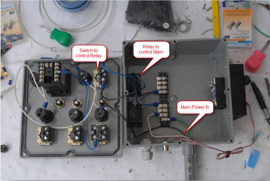
Here is a pic from my build, you can see the main hot(Black) going directly to main power switch, then pig-tailed going to power side of relay. Blue wire from switch goes to control side of the relay. Then a black wire going from the relay to the "Hot" terminal block, that will only be energized if the switch is in the on position:

MainPowerSwitch.jpg
 
Could you share what the dangerous scenarios are so it's less of a conceptual argument? I never made it all the way through the BSEE so I can't get it through my head.

I'm not suggesting one way vs. the other, but I think that calling this a "short" is misleading as it's set up to pull a 120 mA to ground and it's also protected with a fuse. If this is a dangerous way to trip the GFCI, why is it safe to test a GFCI by pressing the test button?

Great questions.


  1. Start by looking on youtube for arc flash. Here's a good one:
  2. The GFCI doesn't create a short to ground; it shunts current around the current sensing coil to create the imbalance that is responsible for tripping the GFCI.
  3. According to code, grounds are not supposed to be current carrying conductors. You are making it a current carrying conductor with this circuit. (It's a bit ironic that all of these P-J diagrams have a disclaimer about NEC.)
  4. This setup also assumes that you have a solidly grounded system. If you don't have a solid ground all you've done is pull everything on your system up to the supply voltage through the resistor and created a shock hazard. This includes all the conductive parts you should be bonding to ground: the metal enclosure, the metal frame, etc. Now you are depending on a person touching something metal on their brew setup to trip the GFCI. Do a little search on google and you can find what percentage of GFCIs actually work. Furthermore, depending on the construction of the E-Stop button, you might have energized parts of it. The button you are pressing to drop power has now become a hazard.
  5. This setup depends on the appropriate selection of components. For example, in the diagram from the original post there are two 1k ohm/1 watt resistors. Let's do the math to verify that they are the correct wattage. Current in the circuit: I = V/R = 120/2k = 0.06A. Power dissipated by each resistor: P = I^2/R = 0.06*0.06/1000 = 3.6 W. The resistors are undersized. Now you have a fire hazard.
  6. What type of fuse are going to use? Are you actually selecting a fuse that is capable of branch circuit protection? I'm going to guess that most people aren't and don't know how to?


This is not an exhaustive list. We could also talk about Short Circuit Current Rating and how this circuit factors into that.
 
Last edited by a moderator:
Great questions.


  1. Start by looking on youtube for arc flash. Here's a good one:https://www.youtube.com/watch?v=Hp1JdVwbN_U
  2. The GFCI doesn't create a short to ground; it shunts current around the current sensing coil to create the imbalance that is responsible for tripping the GFCI.
  3. According to code, grounds are not supposed to be current carrying conductors. You are making it a current carrying conductor with this circuit. (It's a bit ironic that all of these P-J diagrams have a disclaimer about NEC.)
  4. This setup also assumes that you have a solidly grounded system. If you don't have a solid ground all you've done is pull everything on your system up to the supply voltage through the resistor and created a shock hazard. This includes all the conductive parts you should be bonding to ground: the metal enclosure, the metal frame, etc. Now you are depending on a person touching something metal on their brew setup to trip the GFCI. Do a little search on google and you can find what percentage of GFCIs actually work. Furthermore, depending on the construction of the E-Stop button, you might have energized parts of it. The button you are pressing to drop power has now become a hazard.
  5. This setup depends on the appropriate selection of components. For example, in the diagram from the original post there are two 1k ohm/1 watt resistors. Let's do the math to verify that they are the correct wattage. Current in the circuit: I = V/R = 120/2k = 0.06A. Power dissipated by each resistor: P = I^2/R = 0.06*0.06/1000 = 3.6 W. The resistors are undersized. Now you have a fire hazard.
  6. What type of fuse are going to use? Are you actually selecting a fuse that is capable of branch circuit protection? I'm going to guess that most people aren't and don't know how to?

This is not an exhaustive list. We could also talk about Short Circuit Current Rating and how this circuit factors into that.

The video shows a very scary flash for sure, but there is no explanation at all as to how pulling about 100 mA of current in a closed metal box is going to create an arc flash of any kind, nevermind one that is so dramatized in that video. Are you suggesting the setup in PJ's diagram can do what this video is showing? If not, it's more of a scare tactic when used in this discussion no?

I'll concede on one very basic fact that the NEC is meant to address. What is the safest possible way to wire something so that safety is maximized when everything that can go wrong, does? In that regard, I agree. At the same time, you have to admit that logically almost everything has to go wrong for this workaround to cause a problem. The resistors would only be powered for more than a second if you hold the button down (or it sticks) AND the GFCI fails. With regard to the assumption that everything is properly grounded.. well, that's kind of a dangerous thing to overlook no matter how you wire an Estop isn't it?

I understand what you mean though.. Assume the ground is disconnected at some point between the main lugs in the control panel back to the GFCI or main. Pressing the eStop button puts voltage on the everything that you thought was grounded.

That's the one situation that I think is most plausibly dangerous.
 
When I built mine I decided to use a 24/12vdc powersupply which controls three 240v/25a 24v switching relays that allow the elements to receive power.
I use the breaker in my spa panel to kill and activate main power to the control panel but there is a switch on my panel to turn the dv power supply on and off. When its off, so are all the relays which normally feed power to my ssrs (both hot leads) I also used a 3 way switch to only allow one of the two main element relays to be active at a time. my third relay only drives a 1000w 240v element for the rims tube and I have changed the connectors on this so it cant be mistakenly miswired with one of the bigger elements at the control panel..
This on top of this I purchased a mushroom estop to use to kill the dc powersupply in case of an emergency. This dc power also powers my pumps/pwm pump speed controllers so essentially the only thing powered up is the pids and my timer if the dc power is off

what my system doesnt take into account admittedly is what would happen if one of my relays somehow fused closed but that is very unlikely.
 
The video shows a very scary flash for sure, but there is no explanation at all as to how pulling about 100 mA of current in a closed metal box is going to create an arc flash of any kind, nevermind one that is so dramatized in that video. Are you suggesting the setup in PJ's diagram can do what this video is showing? If not, it's more of a scare tactic when used in this discussion no?
It's not the 100mA that's the problem. It's the one time that someone mis-wires the E-Stop circuit. 99.9% of the time the circuit will work fine. It's that 0.1% that someone accidentally wires it as a dead short and is doesn't work that is the problem. Also, the circuit isn't contained; it goes through the E-Stop button that's probabaly installed in a penetration in the front of the panel. To answer your question, yes, I am suggesting that P-J's design has potential to do what is in the video.

"Scare tactic"? This implies that I have some intention to manipulate. I just want to make people aware of the possibilities. I want to help people choose safe, reliable designs for their brewery controls.

I'll concede on one very basic fact that the NEC is meant to address. What is the safest possible way to wire something so that safety is maximized when everything that can go wrong, does? In that regard, I agree. At the same time, you have to admit that logically almost everything has to go wrong for this workaround to cause a problem.
The NEC is really about fire prevention. It's written by the National Fire Protection Association after all. I disagree that "everything" has to go wrong. All the items that I described above are single failures that can create a problem. Murphy's law says that any of these things has potential to happen. So why take the risk?

I appreciate that you recognize P-J's design as a "workaround". :D Even you admit that it's hokey.

The resistors would only be powered for more than a second if you hold the button down (or it sticks) AND the GFCI fails.
E-Stop buttons are maintained buttons--when you press it, it stays in that position. So it's not just for a second.

It may be a simple, clever design. I'll give him that, but it is not something that would be used by an engineer designing a safety circuit, ever. A GFCI is not meant to be used in this capacity. It is meant to protect from shock--not to use a shunt trip. This is not a fail-safe design. When you design a safety circuit, you don't want a failure in the safety circuit to result in a loss of the safety function. In this case it can.

Why is it necessary to trip the breaker all the way back at your distribution panel anyway. That's just a PITA. There are appropriate ways to trip a breaker automatically. It's called a shunt trip.

As you could see, I could go on and on all day about why this is not a good design. There are so many ways that a safety circuit can be design and this not not one of them. This is not a common practice in any professional electrical design.
 
The video shows a very scary flash for sure, but there is no explanation at all as to how pulling about 100 mA of current in a closed metal box is going to create an arc flash of any kind, nevermind one that is so dramatized in that video. Are you suggesting the setup in PJ's diagram can do what this video is showing? If not, it's more of a scare tactic when used in this discussion no?


I'll concede on one very basic fact that the NEC is meant to address. What is the safest possible way to wire something so that safety is maximized when everything that can go wrong, does? In that regard, I agree. At the same time, you have to admit that logically almost everything has to go wrong for this workaround to cause a problem. The resistors would only be powered for more than a second if you hold the button down (or it sticks) AND the GFCI fails. With regard to the assumption that everything is properly grounded.. well, that's kind of a dangerous thing to overlook no matter how you wire an Estop isn't it?


I understand what you mean though.. Assume the ground is disconnected at some point between the main lugs in the control panel back to the GFCI or main. Pressing the eStop button puts voltage on the everything that you thought was grounded.


That's the one situation that I think is most plausibly dangerous.


I see your point, but as you pointed out, if your missing a ground, you will not trip the gfci. I as well as anyone touching or going into a panel, don't want to see ifs or buts. Besides tripping a residential breaker like that can and will wear it out.
 
[*]This setup depends on the appropriate selection of components. For example, in the diagram from the original post there are two 1k ohm/1 watt resistors. Let's do the math to verify that they are the correct wattage. Current in the circuit: I = V/R = 120/2k = 0.06A. Power dissipated by each resistor: P = I^2/R = 0.06*0.06/1000 = 3.6 W. The resistors are undersized. Now you have a fire hazard.

I agree that this is a clever, but kluged, way of effecting E-stop. But let's not get too carried away with the dangers. The resistors would dissipate 3.6 W but only for the couple of milliseconds before the breaker tripped. I^2*R*t would be very small. No fire.

At the same time I like the idea of a disconnect. Were I to do it I think I'd mount a shunt trip breaker to the panel and implement my own GFCI function (using that TI chip or something similar) and OR the GFCI detector with a mushroom head button for the emergency stop.
 
ImageUploadedByHome Brew1412990058.393252.jpg
If you are looking for a main disconnect switch I used one of these rated for the amps my panel will pull. I have the 2 hot legs and neutral running through it. I open the switch before plugging and unplugging the power cord


Sent from my iPhone using Home Brew
 
I am always so entertained by these threads. So many valid points. So many ways to make things a little safer. Just to be a peanut in the gallery I would like to say the following. Mind you I've had a couple tonight so I may not be so eloquent.

I don't want to go into PJ's design as I would work in almost 99% of all possible problems. It is just a redundant GFCI function if one were to have a non ground fault in their equipment. If there were a ground fault the GFCI function 'should' provide its proper protection.

Of course there is always the possiblity for miswiring. We all need to recognize the fact that when we are building these panels we are assuming the responsibility for our own safety.

There is always a chance that our protective equipment will fail. We should be prepared for that outcome. GFCI's fail, breakers stick, or are unable to break the fault current. Sparks flying everywhere, even if someone were to hit the 'oh crap' button even that may not stop the fault.

Those arc flashes are most certainly a possible outcome. As long as you have your panel closed the enclosure should contain the brunt of that though.

All of these things are, none the less, features we put in our system to give ourselves a better chance of avoiding a worst case scenario.

So will all that mindless rambling said have we considered using that E-Stop external to the enclosure? Why short a hot leg to ground when you can just use a DPDT E-Stop and break both hot legs there at the switch, entirely outside of the panel, and maybe 10ft away from your brewing setup. This feature is after all a last resort is it not?
 
This thread seems to be off topic, but I'll throw in my 4 cents worth, being an EE, having worked for a company that made electronics for explosive gas environments, as well as knowing a little about UL, CE, and other approvals.

First off, most people doing their own electric brew systems here could be at risk. This design risk can be minimized by:
1. GFCI circuits always, properly sized.
2. Conductive cases, properly grounded.
3. Proper grounding in the case and on the kettles.
4. Careful construction and wiriring verification.
5. Properly sized wiring.
6. Never power up with the cover off!
7. Have someone(engineer, electrician) check your work.
8. Protection of the wiring and electronics from liquids, dust, explosive gases, etc.

If you think about NEC code for houses, it's all about grounding, wire capacity, electrical shock, and containment in case something goes wrong. Same is true here.

The original post I thought was for a 120V system. I've always thought the contactor and panic stop switch was overkill for those, as you can buy 120V 20 and 30 amp switches for cheap. I do think a separate, 1-2 amp fuse is in order for the PID, lamps, and other low current devices as the wiring and capacity for these are smaller and would not handle the 15-20 amps at which the circuit breaker trips.
Still, I have to aplaud PJ as many would probably not have a system or have burned up if they didn't have a diagram to follow. Seems like his diagrams are relatively safe if built and used correctly.

Disclaimer - everyone should be aware that in building one of these, you are responsible for your own safety, not PJ, me, or anyone else giving advice on this forum.
 
...being an EE, having worked for a company that made electronics for explosive gas environments, as well as knowing a little about UL, CE, and other approvals.

Then you would agree that no reasonable engineer would ever design a system to intentionally ground a current carrying conductor in this manner for this purpose. And I highly doubt UL would approve of that particular design.

I'm an EE that designs industrial control panels on a daily basis. This is not kosher. This would never be acceptable by customers or other engineers.

7. Have someone(engineer, electrician) check your work.
And they would all look at you like you were crazy if you did this.

Like I've already said, there are so many better ways to do it than shorting the hot conductor to ground. I don't understand why you need to trip the breaker at your power distribution panel anyway. If you spec all of your components and wiring correctly there isn't a lot reason to intentionally trip the breaker. If you aren't capable of spec'ing these things then you shouldn't be doing it.

I hate to keep harping on this, but people are putting themselves in harms way for this terrible excuse for an "E-stop" circuit. Oh, the irony. It's maddening that this design keeps getting suggested over and over again without people being aware of the potential.
 
Then you would agree that no reasonable engineer would ever design a system to intentionally ground a current carrying conductor in this manner for this purpose. And I highly doubt UL would approve of that particular design.


I'm an EE that designs industrial control panels on a daily basis. This is not kosher. This would never be acceptable by customers or other engineers.


And they would all look at you like you were crazy if you did this.


Like I've already said, there are so many better ways to do it than shorting the hot conductor to ground. I don't understand why you need to trip the breaker at your power distribution panel anyway. If you spec all of your components and wiring correctly there isn't a lot reason to intentionally trip the breaker. If you aren't capable of spec'ing these things then you shouldn't be doing it.


I hate to keep harping on this, but people are putting themselves in harms way for this terrible excuse for an "E-stop" circuit. Oh, the irony. It's maddening that this design keeps getting suggested over and over again without people being aware of the potential.


I think the thought behind this is this: building the "trip" circuit will trip the breaker the same way the test button on the GFCI does. The manufactures
Of them require a test every 30 days to cover their butts. We know this will trip the breaker, as others have stated, it's not common or safe practice. A breaker is not the same as a contractor wired for safety circuit. Heck even though I have a safety controller, this wouldn't pass for most of the jobs I've done in the nuclear world. I should have 2 contractors in series for each protected circuit.

What we are saying is be safe! And if you don't have the money or knowledge to do it right, then DONT DO IT!!! Most engineers here will not give detailed help because of the liability involved.

If you need help, we are here, but if you want us to design it and assure you that you will be safe..... Well that's not going to happen.

We are not here just beating our chests, we honestly don't want to read of an injury or death from a panel we had input in making.
 
Then you would agree that no reasonable engineer would ever design a system to intentionally ground a current carrying conductor in this manner for this purpose. And I highly doubt UL would approve of that particular design.

I'm an EE that designs industrial control panels on a daily basis. This is not kosher. This would never be acceptable by customers or other engineers.


And they would all look at you like you were crazy if you did this.

Like I've already said, there are so many better ways to do it than shorting the hot conductor to ground. I don't understand why you need to trip the breaker at your power distribution panel anyway. If you spec all of your components and wiring correctly there isn't a lot reason to intentionally trip the breaker. If you aren't capable of spec'ing these things then you shouldn't be doing it.

I hate to keep harping on this, but people are putting themselves in harms way for this terrible excuse for an "E-stop" circuit. Oh, the irony. It's maddening that this design keeps getting suggested over and over again without people being aware of the potential.

I had a long response to this, but my tablet froze and lost it all. So here is the abbreviated version.

Approvals aside:

Yes, I agree the e-stop design is not optimum and is not needed, as another way to shut off power to the system is needed anyway. Looks nice on the panel, however, and will work if all is wired correctly and the GFCI is working.

No, I don't think people are putting themselves in harms way by implementing this feature. There is a 1 amp fuse and a current limiting resistor to limit the energy discharged when the button is pressed. Not at all the same as "shorting the hot to ground".

There are many other things people can do while building and using these control boxes that are way more dangerous, IMHO.
 
Some great info here. Looking for some advice as far as safety is concerned. My setup is a gas HERMS so I'm only using 120V. I thought about just having a main power switch for the entire panel. Any ideas?
 
The GFCI doesn't create a short to ground; it shunts current around the current sensing coil to create the imbalance that is responsible for tripping the GFCI.

The GFCI test button places a resistance across the Hot and Neutral to draw around 5mA of current. One side of this circuit does go through the current sensing coil and the other side doesn't to create the imbalance. I think that was the gist of your message though.
 
My current build has a key switch for main power, went without one at first and had to redo the entire power feed when I decided not having main power on/off bothered me. I used a 1.5 pole contactor and wired a small panel lamp to the always hot. That is the don't go poking around with a screwdriver light, if the panel is plugged in that light is on.
 
The GFCI test button places a resistance across the Hot and Neutral to draw around 5mA of current. One side of this circuit does go through the current sensing coil and the other side doesn't to create the imbalance. I think that was the gist of your message though.

Yes. That is what I said:

it shunts current around the current sensing coil to create the imbalance that is responsible for tripping the GFCI.
 
Back
Top