• Please visit and share your knowledge at our sister communities:
  • If you have not, please join our official Homebrewing Facebook Group!

    Homebrewing Facebook Group

BruControl: Brewery control & automation software

Homebrew Talk

Help Support Homebrew Talk:

This site may earn a commission from merchant affiliate links, including eBay, Amazon, and others.
Please tell me about the “connected” property.

I’ll post the script later.

Script attached to this message. The sleep command was originally after the devices were enabled. I moved it to the beginning of the script now, but i haven't tested it yet because my brewery is not at my house. I will be able to test later tonight though.
 

Attachments

  • script.txt
    6.6 KB
@HobbyBrauer... I keep replying out of order!

Anyhoo... awesome, glad you got it worked out.

Regarding the 0-255 native PWM range: the MEGA is an 8 bit micro. 2^8 is 256, aka all values 0-255. Having higher resolution is to your benefit, as you will have finer control in critical applications. With 0-100, you couldn’t dial in decimals if needed. Like the Geico commercial, you get more!

Some micros have even higher resolution, so we’ll be able to accommodate that through the calibration system.

Questions on PID and PWM..

1 - PID using Mega outputs 2,3 for PWM analog board control of a Johnson (VA9104-GGA-2S) 0-10v valve bench testing seems to like Kp(0.05) Ki(.1) Kd(0.1) to start out, using just a method of changing the target 1 degree above, then below the controlled temp. The 30/1/5 values suggested in the manual resulted in full on, full off..

2 - If I reverse the control of the PID to have the output do cooling instead of heating, I am seeing -255 on my PID display, and the analog board is putting out 0v all the time.. I can workaround this by not using 'reverse control', and opening up my 0-10v analog valve and flipping a dip switch, but shouldn't reversing output on a PID that is on a PWM channel make it change from 0-255 to 255-0? what is -255 in PWM?
 
Using PID for valve control? I haven’t tested it but I would imagine you need very long cycle windows to prevent the valve from making a lot of changes. The proportional gain might need to be turned way down and let the integrator work.

I think for valve control, a script is better.
 
it works with a normal PID(with analog output), it moves a tiny bit quite often, but it works great.

I feel that I should be able to get the output of the PID to have a curve or even sine wave when I test by using a script to change the target to above and below the temperature... all I can do is get a square wave or sawtooth when doing this...

I ran a bunch of tests this morning and documented them, and cannot get the I or D to function as a PID should... it did not translate well to inserting here and I do not want to hijack the thread with such a long post, so I will just attach a PDF of the Word Doc here.

(see attached PDF)
 

Attachments

  • PID Tuning.pdf
    1.1 MB
Analog input question - I can ground them, tie them to 5v, put a 10K-10K voltage divider to 5v, but they always show as 1023... Any clue as to what i am doing wrong? enabled, no calibrations, tried 5 different ones... about ready to try a different mega or my feather M0

edit: analog input 1 (101)Feather M0 on my desk works..
edit2: neither Mega's analog inputs seem to work (sunfounder from amazon)
 
Last edited:
Last edited:
OK, since tying the AREF to 5v worked on my desk unit, I hooked it up on my production one, and then changed the graph to compare the target to the analog input, and think I have something I can start working with (I saw no round curves whatsoever when monitoring the 'PID' via the graph...:
upload_2018-12-9_11-19-43.png
 
I've been following the development of this system for a few months now, and have been very impressed with the progress and response. Kudos to you, BrunDog, for bringing a well thought out and supported system to a niche market like homebrewing. Working with Allen Bradley/Rockwell systems for my day job, its nice to be able to bring similar functionality home in a small, low cost form factor. Any interest in bringing Particle into the mix? Looking forward to upgrading my control system next year!

Cheers,
Joe
 
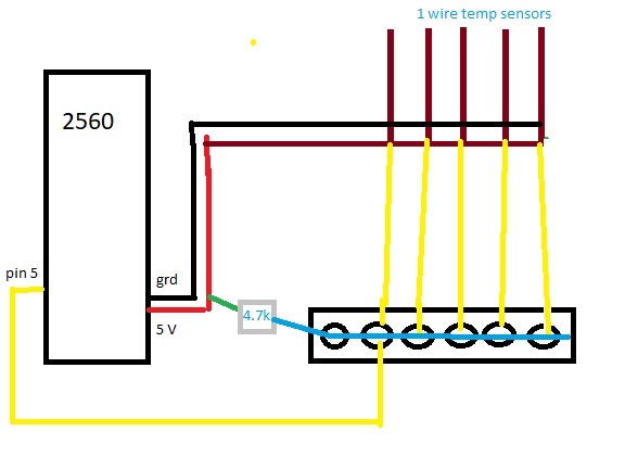
I sure could use some help, I have been at this for days. I am new with Bru Control , love it so far but I am having issues with the DS18b20 temp sensors. I have 5 but can only read 3. When I hook up the 4th sensor, all readings go flat --------- and dont display anything. I have tested each sensor independently and all read normally. I have 2 mega 256's and it is same on both interfaces. The wiring is the same, I have tied all the grounds together, tied the vcc together and add one data line at a time. the first three of any sensors will read, but the 4th knocks them all off. I have an extra power supply connected. I have sequenced each device at 0,1,2,3 , data is on pin 5 and using port 200. And suggestions will be greatly appreciated.

thanks all

KDAZ
 
what is AREF.... (feeling dumb right now... and think I am about to learn something)

edit: no mention of AREF in the latest BC manual... (using ctrl+f at least)

edit 2 - Reading https://www.arduino.cc/reference/en/language/functions/analog-io/analogreference/ says the default should cover it, but I put a jumper on and BAM.. it works

We try not to get into specifics of wiring etc. in the manual since micro-controllers have a lot of variation between units. Please see the Schematics or the Interface Wiring Map for reference to AREF.
 
I sure could use some help, I have been at this for days. I am new with Bru Control , love it so far but I am having issues with the DS18b20 temp sensors. I have 5 but can only read 3. When I hook up the 4th sensor, all readings go flat --------- and dont display anything. I have tested each sensor independently and all read normally. I have 2 mega 256's and it is same on both interfaces. The wiring is the same, I have tied all the grounds together, tied the vcc together and add one data line at a time. the first three of any sensors will read, but the 4th knocks them all off. I have an extra power supply connected. I have sequenced each device at 0,1,2,3 , data is on pin 5 and using port 200. And suggestions will be greatly appreciated.

thanks all

KDAZ

Are all power supply grounds tied together? Are all sensors' VCC and Data lines tied together via one 4.7k resistor? If so, maybe try a 2.2k resistor. Is the external PS 5V (verified by a meter)? Pics/schematics help.
 
Using PID for valve control? I haven’t tested it but I would imagine you need very long cycle windows to prevent the valve from making a lot of changes. The proportional gain might need to be turned way down and let the integrator work.

I think for valve control, a script is better.

Not sure what sort of script you are talking about, but I don't think that a script will hold a tenth of a degree in a container by controlling cooling(or heating) water, and an off-the shelf PID with a few tuning steps does it pretty easily.....

Controlling a proportional valve was the entire reason my otherwise fine for 9 years BCS-462 did not work for me.... You probably saw me beg them for 4-20mA/2-10v or even enable the hardware PWM(500-1000hz, good enough for analog voltage) that the existing chipset was very capable of doing...
 
Well, maybe you do want a lot of dynamic changes hence the reason for using PID. I honestly don't have any experience in this application, but the algorithm will certainly work - just need to tune it. By all means I am looking forward to you teaching us some cool new stuff.
 
it works with a normal PID(with analog output), it moves a tiny bit quite often, but it works great.

I feel that I should be able to get the output of the PID to have a curve or even sine wave when I test by using a script to change the target to above and below the temperature... all I can do is get a square wave or sawtooth when doing this...

I ran a bunch of tests this morning and documented them, and cannot get the I or D to function as a PID should... it did not translate well to inserting here and I do not want to hijack the thread with such a long post, so I will just attach a PDF of the Word Doc here.

(see attached PDF)


You might want to try Ziegler-Nichols method to do the tuning i.g. as explained in this youtube video. The result will get you close to good tuning values, if its a bit aggressive you can use the alternative formulas from the wikipedia site.

It's crucial for a good result that the input sensor is as close to the valve as physically possible by that I mean that you want to make the time from the valve position changes to the temperature sensor senses the load change to a minimum. Every second the time delay increases it makes the tuning harder and if its too long the PID controller will be unsuitable. The tuning will always be a compromise of over/undershooting and valve traveling too much and too often but I believe it will work out pretty good with proper tuning. If there is noise from the input sensor I would consider being very careful with the Kd value. If its noisy it will amplify the noise to the output. And also, I guess thats because it didn't make any change to the output in your trials since it won't react on setpoint changes, it will only react based on if the input inclines/declines and the derivative of the changes.
 
I understand tuning PIDs, this is just not acting as expected at the moment (I cannot check full closed loop with feedback right now, until I finish the panel electrics.) Here is a thread on the stilldragon forum of me implementing this 4 years ago with the Sestos D1S-CR analog output PID, which has funky values, such as using t for the derivative.... so I know I have some work to do to understand the conversion from them to this.

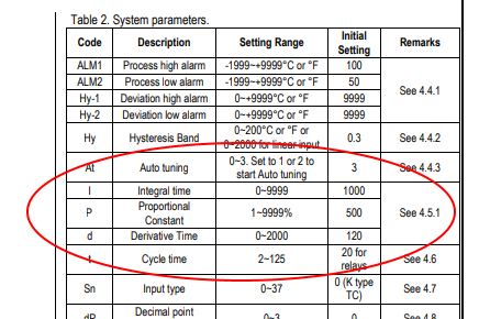
Sestos is close to auber, and here is an excerpt from The Auber Instructions:

upload_2018-12-10_10-22-1.png


I understand sensor and valve placement, actually valve is not quite as critical(you stop flow in one place in the loop, you stop it everywhere), but sensor is very critical, similar to a RIMS controller requiring it be a close to and above the heater element as possible to measure temp changes quickly even with small flow. For a still reflux condenser, the best placement is a probe inserted right into the condenser, where the heat source is(condensing vapor), as this will read correctly no matter the flow...

My issue is that the Kp,Ki,Kd are not acting as I expect them to, but it could be 100% my fault.. I expect that even with no feedback,(the temperature does not change, a condition that would also happen if you were using this for RIMS and either the SSR/heater was not connected/working or the temp prove was not inserted..) that:
  • With a small Kp and even a tiny Ki, the output would increase over time to get to 100% output... it does not... it rises, then plateaus, which is similar to no integral component...
  • Increasing or decreasing the Kd would flatten out the output and eliminate quick changes. it does not..
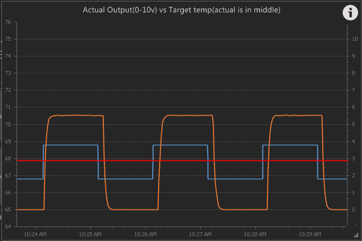
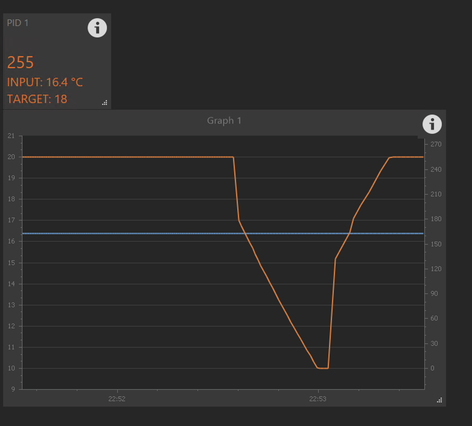
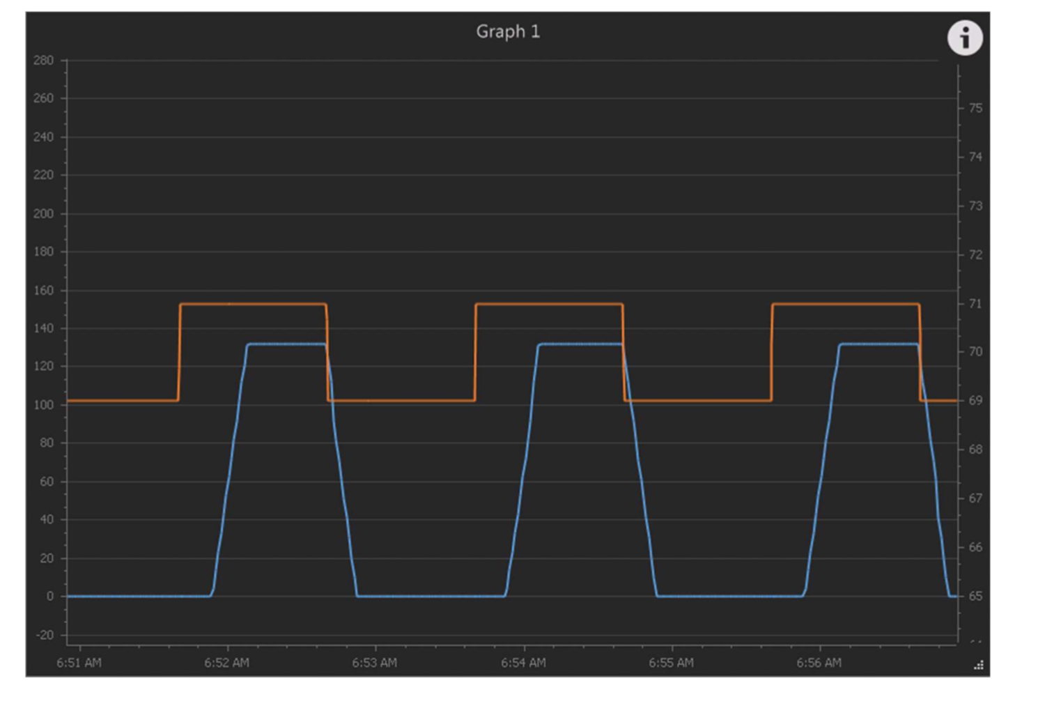
Here is a graph of the analog output measuring actual output of the 0-10v usign a 10k-10k voltage divider to the Mega(Orange line is 0-10V), and a script changes the target temp (Blue line is 66.8 to 68.8F swing) the actual temp is the red line (added by hand at 67.8F)

Changing Kp or Ki *do* change the amplitude of the output, but I *think* that any Kp and Ki value greater than zero should keep increasing and increasing the output over time to 100% output. Also, increasing the derivative should eliminate those sharp transitions... in reality, changing Kd does nothing that I can see... I think I should be able to get a sinusoidal output, but that ain't going to happen if I cannot smooth out the harsh changes.
upload_2018-12-10_10-34-2.png


I have to go to NC for holiday family visit for a week tomorrow, but will try to research how the Arduino MEGA actually implements the PID compared to a discrete PID controller...
 
I am following this as well. Since I have some small issues with my HERMS PID settings, and have been scratching me head.
 
Some comments:

1. The PID algorithm is not complicated math, though trying to understand its response can be. If you want to look under the hood, you can connect serial monitor (terminal) and enable Debug level 2. It will report PID calculations.
2. "With a small Kp and even a tiny Ki"... yes, the integral component will build over time, creating a 100% output condition. If you are not seeing that, meaning a terminal condition where the target is never achieved, it could be that the Ki is too tiny (insignificant to add) or you have your "Max Integral Output %" limited to less than 100%.
3. "Increasing or decreasing the Kd would flatten out the output and eliminate quick changes." Increasing, not decreasing the derivative component will reduce quick changes. Remember that change will get tracked in proportional error, and the derivative is there to dampen it.
4. I don't really understand your graph. The interface cannot provide 10V output no matter how you voltage divide. Also the red line never changes, so it can't possibly be your input.
5. "research how the Arduino MEGA actually implements the PID". Unfortunately there really isn't anything to research. The MEGA is not responsible, our FW code is, and the MEGA just follows it. The code does not use the published PID library, but they are essentially identical in terms of calculations.

Maybe send me your .brucfg file and I can take a look to see how your PID is set up. I'm happy to do a video to demonstrate how the PID responds to inputs as well.
 
I understand tuning PIDs, this is just not acting as expected at the moment (I cannot check full closed loop with feedback right now, until I finish the panel electrics.) Here is a thread on the stilldragon forum of me implementing this 4 years ago with the Sestos D1S-CR analog output PID, which has funky values, such as using t for the derivative.... so I know I have some work to do to understand the conversion from them to this.

Sestos is close to auber, and here is an excerpt from The Auber Instructions:

View attachment 601736


I understand sensor and valve placement, actually valve is not quite as critical(you stop flow in one place in the loop, you stop it everywhere), but sensor is very critical, similar to a RIMS controller requiring it be a close to and above the heater element as possible to measure temp changes quickly even with small flow. For a still reflux condenser, the best placement is a probe inserted right into the condenser, where the heat source is(condensing vapor), as this will read correctly no matter the flow...

My issue is that the Kp,Ki,Kd are not acting as I expect them to, but it could be 100% my fault.. I expect that even with no feedback,(the temperature does not change, a condition that would also happen if you were using this for RIMS and either the SSR/heater was not connected/working or the temp prove was not inserted..) that:
  • With a small Kp and even a tiny Ki, the output would increase over time to get to 100% output... it does not... it rises, then plateaus, which is similar to no integral component...
  • Increasing or decreasing the Kd would flatten out the output and eliminate quick changes. it does not..
Here is a graph of the analog output measuring actual output of the 0-10v usign a 10k-10k voltage divider to the Mega(Orange line is 0-10V), and a script changes the target temp (Blue line is 66.8 to 68.8F swing) the actual temp is the red line (added by hand at 67.8F)

Changing Kp or Ki *do* change the amplitude of the output, but I *think* that any Kp and Ki value greater than zero should keep increasing and increasing the output over time to 100% output. Also, increasing the derivative should eliminate those sharp transitions... in reality, changing Kd does nothing that I can see... I think I should be able to get a sinusoidal output, but that ain't going to happen if I cannot smooth out the harsh changes.
View attachment 601745

I have to go to NC for holiday family visit for a week tomorrow, but will try to research how the Arduino MEGA actually implements the PID compared to a discrete PID controller...


The Sestos is a weird PID. Here is an article from a guy trying to understand its algorithm. Its in Norwegian but google will translate it pretty good.
Back to the BC PID. I am pretty sure it uses the Arduino PID library or similar to do the calculations. How it calculates the output is explained here in post #2.

My issue is that the Kp,Ki,Kd are not acting as I expect them to, but it could be 100% my fault.. I expect that even with no feedback,(the temperature does not change, a condition that would also happen if you were using this for RIMS and either the SSR/heater was not connected/working or the temp prove was not inserted..) that:
  • With a small Kp and even a tiny Ki, the output would increase over time to get to 100% output... it does not... it rises, then plateaus, which is similar to no integral component...
Indeed it shall increase the output to 100% over time, as long as max integral is set to 100%. I did a test run on my own system and it works as expected. I.g with Kp=0.5, Ki=0.05, Kd=0 and error=1 the Kp takes the output to 80 at once the setpoint change is done and after that Ki nicely winds it up linearly to 255. Did not try Kd since I then have to test on a closed loop with feedback.
Some time ago I experienced that my RIMS PID got weird and would not hit setpoint at all. I restarted BC and the interface and it fixed it. Might have been some calculations going wrong or windup I dont know. I used v43 firmware then, v44 now. I think Brundog have done a bugfix regarding PID in v44. The PID calculations are done by the interface I believe. I would've tried upgrading the firmware if not using the latest and/or restarting BC and the interface if not done. Also try to set the max integral to 0%, then make the setpoint change and let the PID find its new output based on Kp. Then set max integral to 100% and you will clearly see the contribution from the integral Ki.

Increasing or decreasing the Kd would flatten out the output and eliminate quick changes. it does not..
Kd will always fight against changes so it will dampen the output if correctly set. But only when the input sensor or feedback responds to the load change. If set wrong it will definitely make quick changes to the output. Take a look at the formula for Kd at the arduino forum post #2 and you'll see that it only looks at changes from the input sensor value and how fast they are. I suggest you start with Kd=0 to rule it out and then use it to fine tune when you have found good Kp and Ki values.

@BrunDog, while testing I found that the PID controller have "wind down induced lag" by that I mean that it integrates the output sub zero on a negative error and when the error gets positive there is a lag before the output starts increasing. To me it looks like the iterm has winded the output down below zero. Something you can fix in the code? Tested wind up lag and there is none, is it because iterm is clamped to max integral which can be 100% max?
 
Are all power supply grounds tied together? Are all sensors' VCC and Data lines tied together via one 4.7k resistor? If so, maybe try a 2.2k resistor. Is the external PS 5V (verified by a meter)? Pics/schematics help.

HI BrunDog, thanks for the help! I will order some 2.2k resistors today and try them. All power tied together, all grounds together, I have a terminal strip connected to pin 5 and place each data line on one at a time that has one 4.7k resistor tied from the Vcc. I can add three sensors on one at a time, and get accurate temps on screen, but when I add the 4th sensor, which is a known good sensor, the screen data on all 4 is ------, no temps, and this from 2 different mega 256 boards. I will measure power supply tonight (same results happened before I added P/S, just running from Mega 5v line) and try the 2.2k res. Will take some images tonight as well. THANKS!
 
HI BrunDog, thanks for the help! I will order some 2.2k resistors today and try them. All power tied together, all grounds together, I have a terminal strip connected to pin 5 and place each data line on one at a time that has one 4.7k resistor tied from the Vcc. I can add three sensors on one at a time, and get accurate temps on screen, but when I add the 4th sensor, which is a known good sensor, the screen data on all 4 is ------, no temps, and this from 2 different mega 256 boards. I will measure power supply tonight (same results happened before I added P/S, just running from Mega 5v line) and try the 2.2k res. Will take some images tonight as well. THANKS!


All sensors have a 4.7k, or they just tie into the one 4.7k going to the BC?
 
HI BrunDog, thanks for the help! I will order some 2.2k resistors today and try them. All power tied together, all grounds together, I have a terminal strip connected to pin 5 and place each data line on one at a time that has one 4.7k resistor tied from the Vcc. I can add three sensors on one at a time, and get accurate temps on screen, but when I add the 4th sensor, which is a known good sensor, the screen data on all 4 is ------, no temps, and this from 2 different mega 256 boards. I will measure power supply tonight (same results happened before I added P/S, just running from Mega 5v line) and try the 2.2k res. Will take some images tonight as well. THANKS!

Just a tip, two 4.7k in parallel will equal 2.35kohm if you want to test before the 2.2k resistors arrive.
 
...

Some time ago I experienced that my RIMS PID got weird and would not hit setpoint at all. I restarted BC and the interface and it fixed it. Might have been some calculations going wrong or windup I dont know. I used v43 firmware then, v44 now. I think Brundog have done a bugfix regarding PID in v44. The PID calculations are done by the interface I believe. I would've tried upgrading the firmware if not using the latest and/or restarting BC and the interface if not done. Also try to set the max integral to 0%, then make the setpoint change and let the PID find its new output based on Kp. Then set max integral to 100% and you will clearly see the contribution from the integral Ki.


Kd will always fight against changes so it will dampen the output if correctly set. But only when the input sensor or feedback responds to the load change. If set wrong it will definitely make quick changes to the output. Take a look at the formula for Kd at the arduino forum post #2 and you'll see that it only looks at changes from the input sensor value and how fast they are. I suggest you start with Kd=0 to rule it out and then use it to fine tune when you have found good Kp and Ki values.

I am using v.43, I hesitated upgrading to the v44 due to the warning:
CAUTION: FOR TESTING/EVALUATION. DO NOT USE IN PRODUCTION ENVIRONMENT.

I will upgrade to v.44... because mind does not wind up... ( see orange line on the above attached graph) of course my WIN7 laptop suddenly cannot see the COM ports in the upgrade tool or device manager, and says the PCI serial driver is missing... worked fine for the last year... and worked fine with the mega directly attached in BruControl... damn windows...
 
[QUOTE="smort, post: 8464019, member:
@BrunDog, while testing I found that the PID controller have "wind down induced lag" by that I mean that it integrates the output sub zero on a negative error and when the error gets positive there is a lag before the output starts increasing. To me it looks like the iterm has winded the output down below zero. Something you can fix in the code? Tested wind up lag and there is none, is it because iterm is clamped to max integral which can be 100% max?[/QUOTE]

Man!! This guy is good! Yes @smort, you are correct. We clamped the integral from zero to max, not negative max to positive max. This means that the integral error will stop at zero if the input is “past” the target. We did this knowing our applications are unidirectionally biases (meaning our kettles heat up actively by the element but have no mechanism to actively cool).

But in truth, a real control system (like a flexible arm on a gear drive positioning a mass into a a specific location) would need the integrator to work in both directions. This makes for a more aggressive system and tuning potentially trickier.

That said, do you want the integrator to work negatively? It will probably make overshoots undershoot more, but if the consensus is desired, it’s a simple switch in the FW. I suppose we could make it a setting in the element properties but that would probably add a lot of user confusion.

Anyway... nothing to see here. Carry on!
 
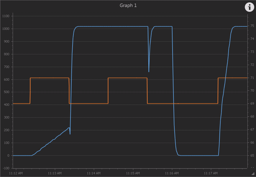
well, it did something... after v.44 upgrade I can now get this(Using the initial 30.0,1.0.5.0 settings), which is closer, but the rapid changes are now what you would see on a discrete PID controller that had any derivative action.. some of the stuff going on is because I am changing the target, not the control temp.. I think when I get back from my trip, I will hook the Sestos up as the controller, and use the Mega temp and analog input to graph what it is doing while it actively controls the valve, then see if I can get BruControl to mimic it, then swap the 0-10v wire from the Sestos to the Mega and see what it does and tune it...

upload_2018-12-10_15-29-53.png

(red line is hand drawn in paint and is the input temp)

Thinking, I guess I could tie an unused analog output (PWM thu amplifier filter) to an unused analog input and have the PID monitor that inut so that my input is changing, but the target is not changing...
 
[QUOTE="smort, post: 8464019, member:
@BrunDog, while testing I found that the PID controller have "wind down induced lag" by that I mean that it integrates the output sub zero on a negative error and when the error gets positive there is a lag before the output starts increasing. To me it looks like the iterm has winded the output down below zero. Something you can fix in the code? Tested wind up lag and there is none, is it because iterm is clamped to max integral which can be 100% max?

Man!! This guy is good! Yes @smort, you are correct. We clamped the integral from zero to max, not negative max to positive max. This means that the integral error will stop at zero if the input is “past” the target. We did this knowing our applications are unidirectionally biases (meaning our kettles heat up actively by the element but have no mechanism to actively cool).

But in truth, a real control system (like a flexible arm on a gear drive positioning a mass into a a specific location) would need the integrator to work in both directions. This makes for a more aggressive system and tuning potentially trickier.

That said, do you want the integrator to work negatively? It will probably make overshoots undershoot more, but if the consensus is desired, it’s a simple switch in the FW. I suppose we could make it a setting in the element properties but that would probably add a lot of user confusion.

Anyway... nothing to see here. Carry on![/QUOTE]

Hmm are you sure the integral minimum is clamped to zero? If I set up a PID with a small gain and medium Ki it integrates nice to 100% on a small error. When I give it a small negative error it moves nice down to zero and back up again if I give it a positive error again. But, if I give it a large negative error it moves rapid from 100% to zero, naturally, but if I then from there gives it the same small positive error it takes forever before to output starts to rise from zero, indicating that the integral did not stop at zero? I played with the max integral setting while doing this and to me it seems like the integral is clamped to the negative value of the max integral? I have tested on the Feather and Sonoff maybe its firmware related just to them? I agree with you for a brewery controller the integral should be clamped to zero not negative max.
 
well, it did something... after v.44 upgrade I can now get this(Using the initial 30.0,1.0.5.0 settings), which is closer, but the rapid changes are now what you would see on a discrete PID controller that had any derivative action.. some of the stuff going on is because I am changing the target, not the control temp.. I think when I get back from my trip, I will hook the Sestos up as the controller, and use the Mega temp and analog input to graph what it is doing while it actively controls the valve, then see if I can get BruControl to mimic it, then swap the 0-10v wire from the Sestos to the Mega and see what it does and tune it...

View attachment 601777
(red line is hand drawn in paint and is the input temp)

Thinking, I guess I could tie an unused analog output (PWM thu amplifier filter) to an unused analog input and have the PID monitor that inut so that my input is changing, but the target is not changing...


To me it looks like its behaving normal. The high Kp makes the rapid changes its almost an on/off controller. My example is with error=-0.5 and +1.5 and Kp=0.5, Ki=0.05, Kd=0. I use 2s calc time I guess thats why the initial Kp addition is not a vertical line on the trend.
I wouldn't put any effort in trying to mimic the sestos neither copying or converting its parameters as its a different (and undocumented..) PID equation. The arduino PID equation is not perfect but its better than the Sestos. I would have spent the time at properly tuning the BC PID. There is a lot of resources online how to do it. If you are used to industrial PIDs its a bit different to tune the arduino PID since its using a parallel calculation but you will get used to it. If you're stuck you can flash an arduino with the autotune library just to do the tuning. The values from there will be a good starting point.

Screenshot 2018-12-10 at 22.54.36.png
 
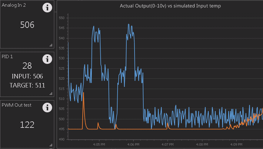
OK, I set up Mega PWM output 3 through the analog amplifier and into Analog 2 and used that as the input for PID1.. on the left side, I was cycling the output simulating changing temp, and saw those blips, thinking it was still not operating...

I stopped the script on a thought to just see what happens, and let the PWM output sit at 122(0-255) and the analog in shows 506(0-1023) a minute later, there is the rise I was looking for....

now to tune... this was with 30,1,5,

upload_2018-12-10_16-12-4.png


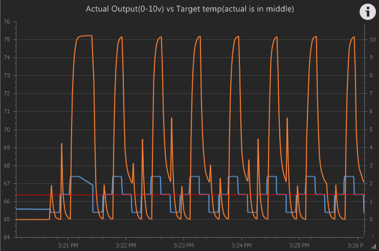
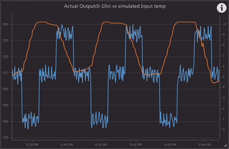
and taking Kd to .1 after a couple steps made the orange line nice and smooth... then tweaked a few other things... the biggest issue may have been the 'Max Integral%' being left at the default of 50... when I took it to 100%, it actually started winding up on error..


here is Kp=.01, Ki=.16. Kd=.002 max integral=100%, calc time of 5... for not being a true closed loop, this will be a good starting point...

upload_2018-12-10_17-45-19.png


I have worked with PID's in everything from college engineering classes to programming and repairing old-school analog PID's in Caterpillar engine test cells in the 90's yes, the Sestos is goofy, I do not know to much about the arduino one, and how it is implemented... but I think I have it close, I want it to be able to max out in either direction, but take a good long time to get there, like 20-30 seconds...
 
OK, I set up Mega PWM output 3 through the analog amplifier and into Analog 2 and used that as the input for PID1.. on the left side, I was cycling the output simulating changing temp, and saw those blips, thinking it was still not operating...

I stopped the script on a thought to just see what happens, and let the PWM output sit at 122(0-255) and the analog in shows 506(0-1023) a minute later, there is the rise I was looking for....

now to tune... this was with 30,1,5,

View attachment 601786

and taking Kd to .1 after a couple steps made the orange line nice and smooth... then tweaked a few other things... the biggest issue may have been the 'Max Integral%' being left at the default of 50... when I took it to 100%, it actually started winding up on error..


here is Kp=.01, Ki=.16. Kd=.002 max integral=100%, calc time of 5... for not being a true closed loop, this will be a good starting point...

View attachment 601801

I have worked with PID's in everything from college engineering classes to programming and repairing old-school analog PID's in Caterpillar engine test cells in the 90's yes, the Sestos is goofy, I do not know to much about the arduino one, and how it is implemented... but I think I have it close, I want it to be able to max out in either direction, but take a good long time to get there, like 20-30 seconds...

This looks good seems like you're on track to get it going with BC. I peaked a bit more on the trends you posted earlier e.g this one, I notice that when you increase the setpoint there is a lag before the output starts to increase. The same lag is not there when decreasing setpoint and the output starts to decrease. That might be the same issue I saw when testing which might be related to integral clamping, what do you think @BrunDog ?
Screenshot 2018-12-10 at 23.55.25.png
 
Fun Fact, seeed studio w5500 shields do come with mac addresses, however the require the 5v pin (not the one on the icsp bus) to work. Doesn't matter when used as it should be stock.. but does if you modify it.
 
BrunDog,

I put the 2x 4.7k resistors in parallel and now i get all 5 sensors working. Will read the manual to learn how to calibrate them next. Thanks for your help on this!

KDAZ
 
Back
Top