• Please visit and share your knowledge at our sister communities:
  • If you have not, please join our official Homebrewing Facebook Group!

    Homebrewing Facebook Group

Electrical Primer for Brewers

Homebrew Talk

Help Support Homebrew Talk:

This site may earn a commission from merchant affiliate links, including eBay, Amazon, and others.
I just looked at my dryer outlet, and it's a 30A 250V outlet. But I'm not sure if it is the 4 prong or 3 prong w/ no ground. There are 2 flat prongs, 1 prong that is L shaped, and a circle in the middle of the outlet which looks like it might be for a 4th prong. Any ideas? I might just have to turn off my main breaker and have a look inside the outlet

The two flats are hot, the l shaped is neutral. If you look in the 'middle' one you should see a screw unless it is missing. A 4 prong with ground is not laid out that way.
 
Can we expect another installment after the holidays/new year? This is really good stuff!
 
Regarding the dryer outlet, I use one of those. I just use the middle wire as the ground and everything tests out ok.

In theory they are the same thing but reality can be different. WAY to many variables to go into but if the transformer outside your house loses ground then, in theory, your voltages (including neutral) could rise to some seriously dangerous levels. That is why modern code has it as a separate line independent of what the power company provides. When I had my breaker box replaced I was surprised at the effort the guy went through to provide redundant grounds. Also, in theory, even if the neutral is grounded at the transformer, ground potential between your house and the pole can be different.
 
Will a gfci breaker circumvent the danger you mentioned, or is the danger inherent anyway since you're stating the ability of a safe ground isn't really there?
 
Will a gfci breaker circumvent the danger you mentioned, or is the danger inherent anyway since you're stating the ability of a safe ground isn't really there?

I'm not an engineer, but if you have a faulty "ground" then I'm not sure a ground fault protector would work right. In the case I mentioned the whole system would float above ground potential but maintain their relative values.

I had a friend that worked for a company that the electrical system was designed by a Russian immigrant. Contractors would come in and try and drop a 120 volt outlet off a hot line by running the neutral directly to ground only to find the voltage was NOT what they expected because the system as a whole was not grounded. It "floated".

Bottom line? If your life or safety depend on it, run a reliable ground.
 
In Soviet Russia, system wires you!

Well, the way I see it, my dryer has been fine for the 20 years it's been on this circuit, so I hope the brewery is. I've also seen many other systems that use the same method that I have....however, these guys haven't updated their blogs in a while...
 
gfci's are current based, not potential based. The current measured on all legs must be accounted for, so for simplicity's sake lets say 100mA is going out on leg 1 the gfci expects to see approx 100mA on the neutral. If there is only 95mA on the neutral the gfci recognizes that 5mA of current has found an alternate path to ground and trips. (This is the ground fault, not so much there is a problem with the provided ground but current has found an alternate path to ground) This alternate path could be a person getting shocked, a march pump leaking current to the grounded chassis, a loose wire on the control panel making contact to ground, etc etc.

As far as updates go, I am compiling a large document and sets of drawings, The info has become a bit scattered in this thread. I'll start a new thread and put it all in there. Perhaps the wiki too, but that is new territory for me.
 
In Soviet Russia, system wires you!

Well, the way I see it, my dryer has been fine for the 20 years it's been on this circuit, so I hope the brewery is. I've also seen many other systems that use the same method that I have....however, these guys haven't updated their blogs in a while...

Like I say, there is a difference between practice and theory. It would be an unusual circumstance for the neutral not to be grounded, but I'm not trained nor do have the equipment to do the testing if I was there, let alone across the net. That is why I said, if you life or safety depend on it, ensure you have a good ground.
 
gfci's are current based, not potential based. The current measured on all legs must be accounted for, so for simplicity's sake lets say 100mA is going out on leg 1 the gfci expects to see approx 100mA on the neutral. If there is only 95mA on the neutral the gfci recognizes that 5mA of current has found an alternate path to ground and trips. (This is the ground fault, not so much there is a problem with the provided ground but current has found an alternate path to ground) This alternate path could be a person getting shocked, a march pump leaking current to the grounded chassis, a loose wire on the control panel making contact to ground, etc etc.

As far as updates go, I am compiling a large document and sets of drawings, The info has become a bit scattered in this thread. I'll start a new thread and put it all in there. Perhaps the wiki too, but that is new territory for me.

So if you 'short' to neutral all current is still accounted for then? Still that is much better than short to laundry tub with you as the conductor I guess. :D
 
So if you 'short' to neutral all current is still accounted for then? Still that is much better than short to laundry tub with you as the conductor I guess. :D

Yeah, but at that point the actual amperage rating of the breaker will pop. I would almost bet dollars to donuts that the gfci would trip too just because of the sudden surge. So I guess the moral of the story is dont wear rubber boots if you plan to grab a hot and neutral in each hand :)
 
Yeah, but at that point the actual amperage rating of the breaker will pop. I would almost bet dollars to donuts that the gfci would trip too just because of the sudden surge. So I guess the moral of the story is dont wear rubber boots if you plan to grab a hot and neutral in each hand :)

Yeah. Just trying to cover bases here. I once told a guy to short a switch to test it. Very hard to get to the switch so I told him there are two big white wires from it coming down behind the unit. One on the left, one on the right. Jump it there.

Next time he saw me he was all upset because he did as I instructed him. He took the white and black wire from the ceramic block and tied them together and it popped the breaker? Even if I HAD told him to short the light bulb he should have known better. Guy was head of maintenance for over 1000 units.....
 
Great thread and thanks!

Trying to set up something similar to what The Pol did with his electric BK. However the only available 240V outlet is 3-prong. Therefore:

1. There are 2 HOT's 180 degrees out-of-phase. This is the 240V portion
2. There is a ground.
3. No neutral which means I cannot wire up a 120V outlet on the control box to power a pump.


Thanks for any tips.

I would suggest to anyone working with electricity to simply buy an inexpensive meter and learn to use it. Unless you take the cover off of your fuse box it will be difficult to tell, but most of those setups have a neutral, not a ground. Even if it is a bare connector at the box it could still have been run to the neutral bar.

That said, a proper ground can be used as a neutral in most applications. That is why I suggest a meter. Would it be hard to run another wire back to your box?
 
Understood about the meter! Just can't test right now, it's at the apartment, and I am not. Will check later.

Because I do rent, it is hard to run a ground back.

In those old 3 prongs is the non-HOT wire a neutral tied to ground? So you can run 120V items off of it?

If in the future, I move and end up with a 4-prong it would probably be best to wire everything up 4 prong and then just use a piggy tale setup for the apartment now.
 
I would suggest to anyone working with electricity to simply buy an inexpensive meter and learn to use it. Unless you take the cover off of your fuse box it will be difficult to tell, but most of those setups have a neutral, not a ground. Even if it is a bare connector at the box it could still have been run to the neutral bar.

I agree 100%
If you are building your own rig and wiring it yourself please get a meter to test with. Simply wiring something in backwards is often enough to permanently damage a motor. It is good for all kinds of things like seeing if the circuit breaker you thought was the one for the socket really was (you can test the socket).

As for the 240V with no neutral it is more likely this is a more then 15 year old plug with the neutral and ground together. There would have been a green wire that was run from the socket to whatever was plugged in to act as ground. After a few people died and many accidents occurred NEC changed that code in 1996.

If you want to use the plug, rewire it so that is has both hots, a neutral and ground. It is not that difficult to rewire, just expensive as the copper wire costs money.
 
Understood about the meter! Just can't test right now, it's at the apartment, and I am not. Will check later.

Because I do rent, it is hard to run a ground back.

In those old 3 prongs is the non-HOT wire a neutral tied to ground? So you can run 120V items off of it?

If in the future, I move and end up with a 4-prong it would probably be best to wire everything up 4 prong and then just use a piggy tale setup for the apartment now.

Years ago when electronic light dimmers were making their way into theaters I witnessed a 'discussion' between a road technician and the 83 year old 'house man' of the theater. The roadie insisted he had to have a separate ground from the neutral. The stage hand told him the neutral for the theater was grounded to the same beam he wanted the hole drilled in anyhow.

http://en.wikipedia.org/wiki/Ground_and_neutral


Hermit - are you saying that neutral and ground were connected for a very long time prior to 1996 and thus should not be too big of a deal from a stove 3-prong plug to run 240V to a 3 pole dist. block and then run the 240V 5500W element off it and wire it for a 120V March pump as well?
 
I agree 100%
If you are building your own rig and wiring it yourself please get a meter to test with. Simply wiring something in backwards is often enough to permanently damage a motor. It is good for all kinds of things like seeing if the circuit breaker you thought was the one for the socket really was (you can test the socket).

As for the 240V with no neutral it is more likely this is a more then 15 year old plug with the neutral and ground together. There would have been a green wire that was run from the socket to whatever was plugged in to act as ground. After a few people died and many accidents occurred NEC changed that code in 1996.

If you want to use the plug, rewire it so that is has both hots, a neutral and ground. It is not that difficult to rewire, just expensive as the copper wire costs money.

I can not rewire the outlet, I rent and while the landlord likes me, he does know I am not a certified electrician.

There is an electrician at work I can talk to who will give me a hand, I just want to get this all figured out (at least make sense to me) before I go and ask him what he thinks (and buy parts).
 
Hermit - are you saying that neutral and ground were connected for a very long time prior to 1996 and thus should not be too big of a deal from a stove 3-prong plug to run 240V to a 3 pole dist. block and then run the 240V 5500W element off it and wire it for a 120V March pump as well?

If this plug is for a stove or dryer then the third wire is almost certainly a neutral and not a 'proper' ground. Each has 120V components. For safety, you can run another ground when you use the unit.

This is why I say use a meter. Check from the third wire, whether it is neutral or ground, and see if you get voltage. Sinks, wall plugs if they have the third wire, copper plumbing, etc. If you get voltage between the two then you have problems. Chances are you won't see anything. Check from a hot to the test ground to make sure it is in fact grounded. But yes, in a properly wired environment neutral and ground are virtually the same. The earth ground is used to have a common reference. If you are pretty far from the transformer or have some other unusual circumstance, then they may not be the same.

Thank you for the advice and info....I'll post the results when I get home.
 
if it's a dedicated stove circuit, you can probably get away with it. but on a circuit with other receps, don't use the bare ground. should a neutral go bad somewhere else in the circuit, there's a potential to get rapped neutral to ground if there's a load on the circuit and you complete it
 
CodeRage, wanted to thank you for putting this together, it has helped a lot in aiding me in getting my RIMS system close to complete!
 
CodeRage, thanks for the excellent write-up. It pretty much confirms everything I know so far, but I do have a nagging question (input welcome from anyone :)). When I finished my garage/shop, I installed all the electrical. There was already a 100a panel, and I installed receptacles for everything I thought I would need to power all my shop tools, welder, etc: several 20a/120v, 20a/240v, 30a/240v. But since I wasn't planning to brew in the shop (and since my rig was all gas at the time), I didn't install a 50a/240v. Now I'm going to be stuck brewing in the shop for the forseeable future and I have to figure out how to get my (completely redesigned) rig wired. Right now I've planned for an electric 5500w HLT and 1500w/120v RIMS element, but this cold winter has me thinking twice about keeping my LP BK and going electric with it as well.

My original plan was to run a GFCI protected 30a feed to the control panel specifically to run the HLT element and my 240v pump, and a separate GFCI protected 20a/120v feed to run the controls, 120v pump, steam solenoid, and RIMS element. Unfortunately, I'm a bit unclear about how the two circuits would interact wrt inductive fields, current leakage, etc. and maintaining good ground fault protection without false trips. I do have the option to fish in a 50a receptacle if that would be easier/safer, but I already have the GFCI breakers and interconnect cable for separate feeds.

Since I haven't seen this idea come up before I thought I'd throw it out there in case there are potential hazards that we all would benefit from knowing.

Thanks! :mug:
MrH
 
Do you have any slots available in your service breaker? You can have more than 100% of the panel rating in total breakers AS LONG as you have a 100 amp main breaker protecting the whole service.

If it is a matter of running the service to the brewery from the box, put a junction box in the wall above it and run the service in conduit to the brewery location.

Personally, I would prefer a sing 240v 4 wire service instead of using two circuits.

I think I answered your question?

Good luck!
 
Okay, apologies for the stupidity of my question, but... well, I'm not that bright, as many of you are finding out.

I spotted the recommendation in the first page of adding a fuse in building a stand's control panel. That said, in scanning the plans for the Brutus 10 (the direction I'm going) Lonnie's not using any fusing in his diagram, so was wondering is I could get a pointer or ten.

Does each component require it's own fuse? (In the case of the Brutus, 2x 0.25A slow blows for the PIDs, and 2x 2.0A slow blow for the march pumps) If so, I assume they would be individually wired after each component's throw switch, using something like this:
pRS1C-2160165w345.jpg

http://www.radioshack.com/product/index.jsp?productId=2062258

Or, would I need to downgrade the amperage coming in at the source?
 
I used a fuse for each component, following CodeRage's amperage recommendations. I prefer these fuse holders:

http://www.radioshack.com/product/index.jsp?productId=2102782

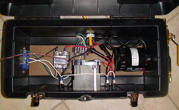
becuase they simplified the wiring, one less jumper to use (unless the length of the leads + fuse holder are too short to use as your jumpers). Here's my rig with the fuse holders in place. Look at the red wires to see the fuse holders easily:
jrfuda_RIMS.jpg
 
Okay, apologies for the stupidity of my question, but... well, I'm not that bright, as many of you are finding out.

I spotted the recommendation in the first page of adding a fuse in building a stand's control panel. That said, in scanning the plans for the Brutus 10 (the direction I'm going) Lonnie's not using any fusing in his diagram, so was wondering is I could get a pointer or ten.

Does each component require it's own fuse? (In the case of the Brutus, 2x 0.25A slow blows for the PIDs, and 2x 2.0A slow blow for the march pumps) If so, I assume they would be individually wired after each component's throw switch, using something like this:
pRS1C-2160165w345.jpg

http://www.radioshack.com/product/index.jsp?productId=2062258

Or, would I need to downgrade the amperage coming in at the source?

Since the PID is an electronic device my guess would be to avoid the slow blow fuse for that.

Quick edit. I'd think the PID had an integrated fuse?
 
Do you have any slots available in your service breaker? You can have more than 100% of the panel rating in total breakers AS LONG as you have a 100 amp main breaker protecting the whole service.

If it is a matter of running the service to the brewery from the box, put a junction box in the wall above it and run the service in conduit to the brewery location.

Personally, I would prefer a sing 240v 4 wire service instead of using two circuits.

I think I answered your question?

Good luck!

Naturally, you gave a perfectly reasonable answer based on the information I gave, which was incomplete :D. My rig is portable, and when I brew I need to roll it about 15' away from my main panel and 240v receptacles. Besides not wanting to try to fish 6ga wire in my brand new finished wall to a new 50a receptacle, I also wasn't looking forward to wrangling 20 feet of 6ga 'extension cord' every time I want to brew, let alone the added cost of buying all that copper. Since I already have over 100' of nice pliable 10/3 and 12/3 stranded cord as well as the required GFCI breakers, I thought I would run separate circuits (cords) to the control panel that is installed on the rig. On brew day I would roll out the rig and plug it in to my protected outlets. My concern is around what that looks like electrically since both circuits would be grounded in the CP. Since they would be fed from separate GFCI's and there's a whole lotta stuff piled in the CP (2 PIDS with room for a third, contactors, switches, SSRs, meters, etc), I'm just wondering if I'm asking for trouble. I'm not overly concerned with electrocution :cross:, but I am concerned about building a reliable CP that doesn't constantly trip one or both GFCI breakers becuase of some inductive interaction I don't understand. Or maybe I'm just overthinking it all. ;)

Thanks-
mh
 

Latest posts

Back
Top