Excellent job EarthBound!! You have a very unique stand built the way you want it. Lots of luck as you finish her! I am thinking of using cam locks also. What letters did you go with on the male and female fittings?
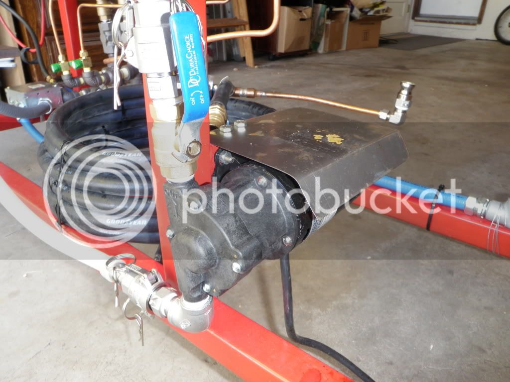
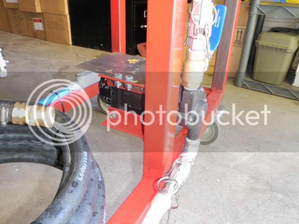
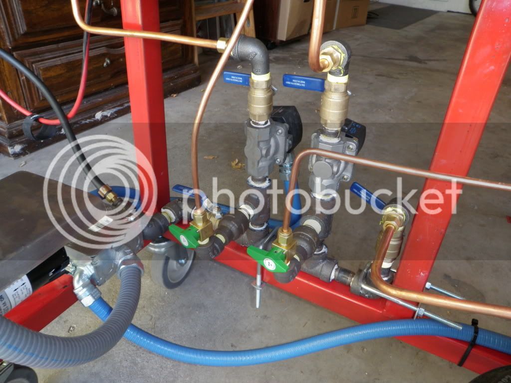
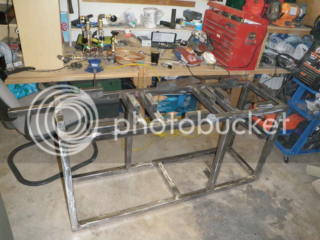
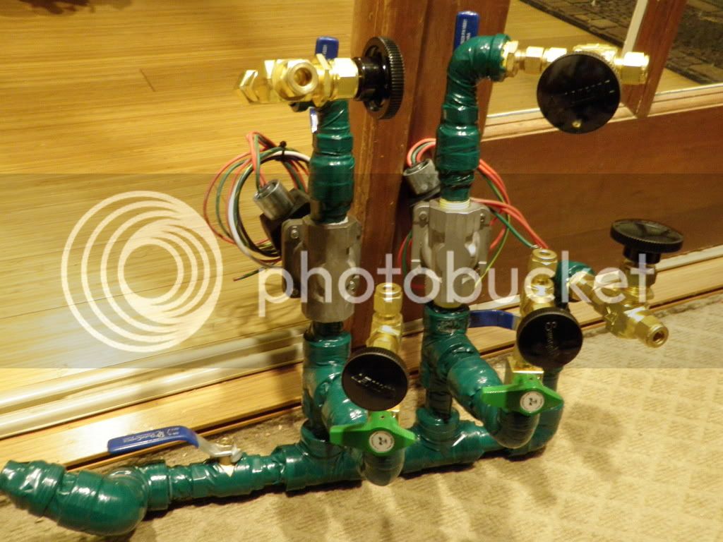
Thank you for your kind words and for making that thread about the valves I now know that I want gate valves for controlling the pump output and the gas too(?). You SHOULD use the camlocks. For the female coupler side, I used part D only. For the male coupler side, I used parts A and F. A screws onto the pumps, and F screws into ball valves. Reference the following parts list for what I was just talking about:
http://www.proflowdynamics.com/documents/cam-and-groove-pricelist.pdf Please note that the prices on that list are outdated; however, they are still an insanely good prices you can buy these in SS for about as cheap as the QDs in brass from McMaster. These camlocks are awesome for flow rate if you follow bobby ms instructions on grinding down one side of the nipples, and the other side is screwed into part D. Im going to buy more of them simply because I love them so much and plan on using more of them for future upgrades
that was my proflowdynamics plug: Brought to you by Carls, Jr.

Lookin' good, man! What was your old setup? How did it compare to your new one with respect to 1. brewing time, 2. consistency, 3. ease of use? I'm on the last leg of my new build as well, but haven't gotten far enough to brew yet. TB
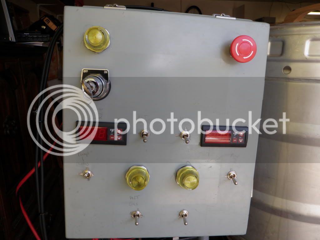
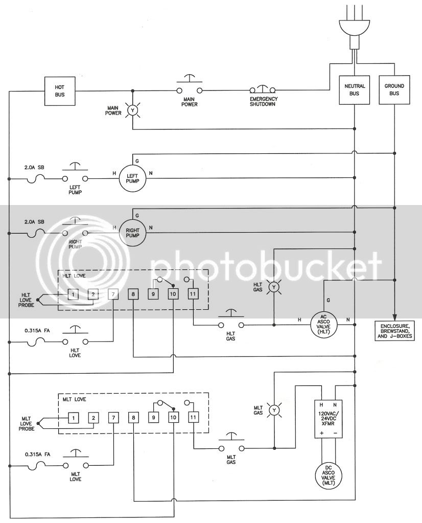
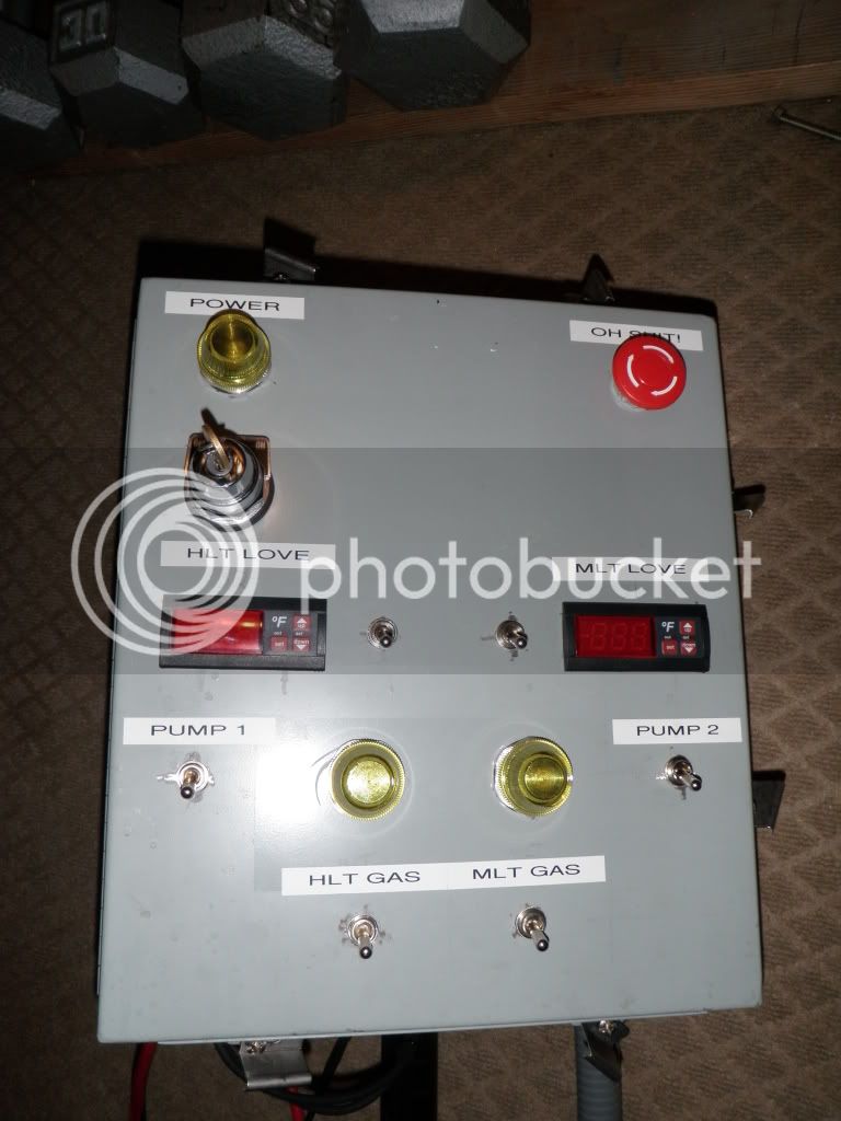
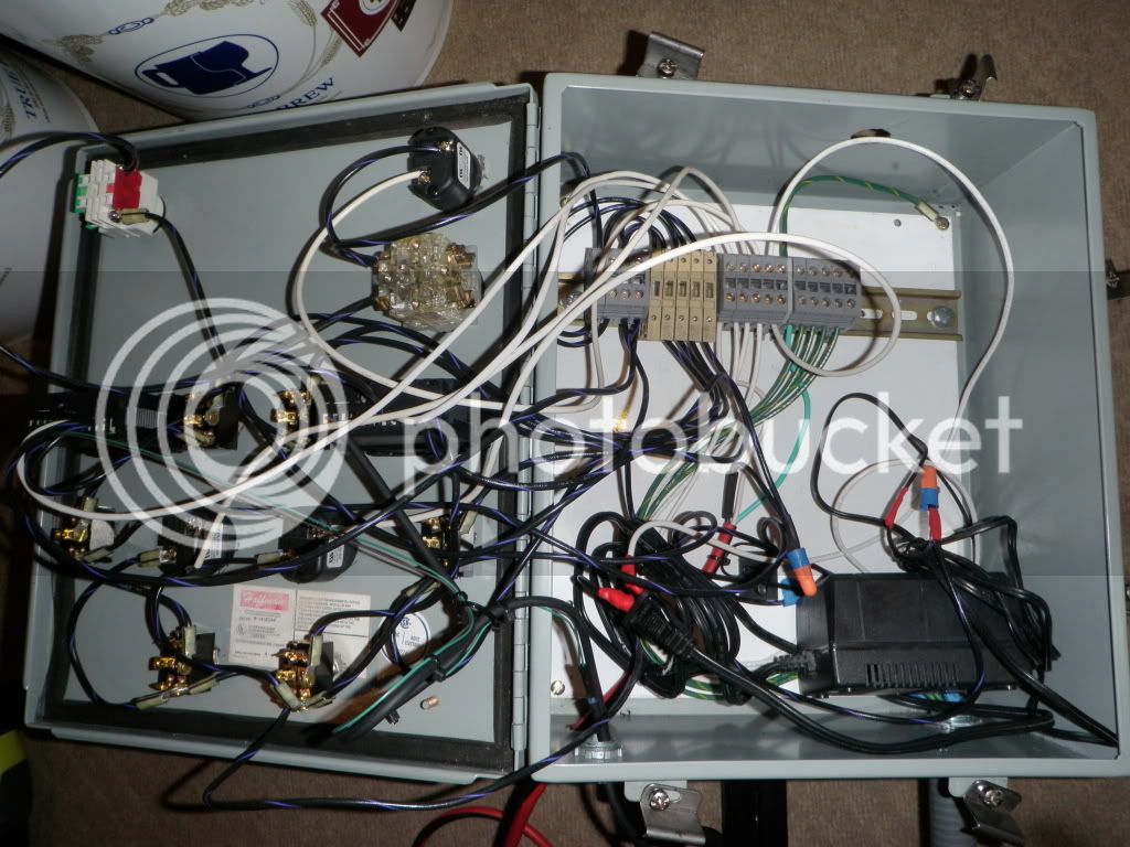
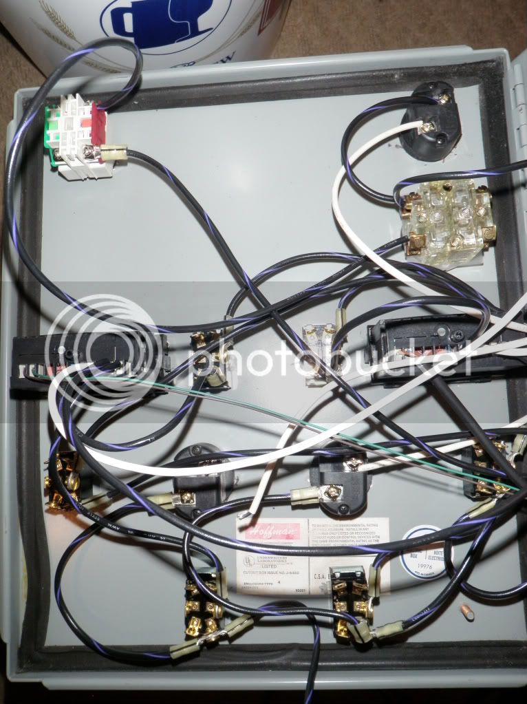
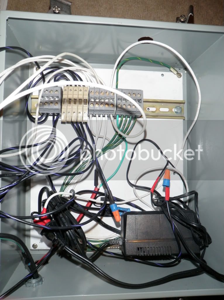
Thank you! Your control panel is a thing of beauty, and I will definitely reference your wiring diagram. I'll post my wiring diagram soon. Youre doing an amazing job, bro. You will be very happy when youre done. Trust me.
1. Brewing time is shortened by about a couple hours.
2. Consistency is the keyword with automation
you can set temps as opposed to hoping you hit them. Its more like clockwork and a lot less chances of wasting time because of mistakes.
3. Its still hard to get used how easy this is because there is so much less work involved. Instead of lifting hot and heavy liquid, I flip a switch and have a homebrew. Instead of constantly checking and adjusting temps, I push a couple buttons and have a homebrew.
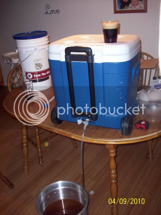
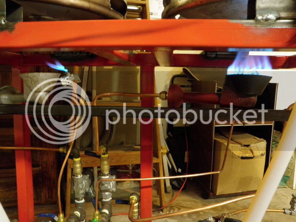
Heres some pics of my old setup
Heating up strike and sparge water:
Draining MLT:
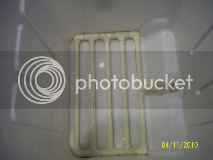
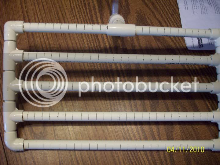
CPVC manifold in MLT:
Closeup of manifold. It works unbelievably well. Very easy to make.
You mentioned that the infrastructure should be a few inches shorter, what do you think would be the best height for the stand?
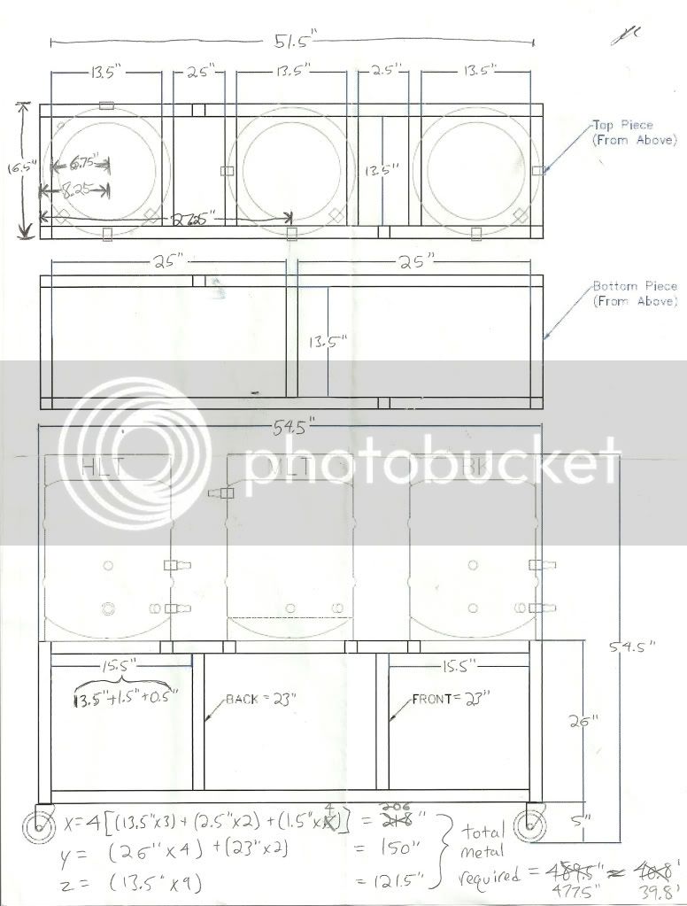
It depends on your height, and how much you intend to shove within the brewstand. Ive seen someone fit his keggles within the infrastructure, and I think that its a great innovation, but not for me. To answer your question with a number, please see diatonics schematic that I referenced when building mine:
https://www.homebrewtalk.com/f51/my...ybrid-brew-rig-160432/index4.html#post1906952
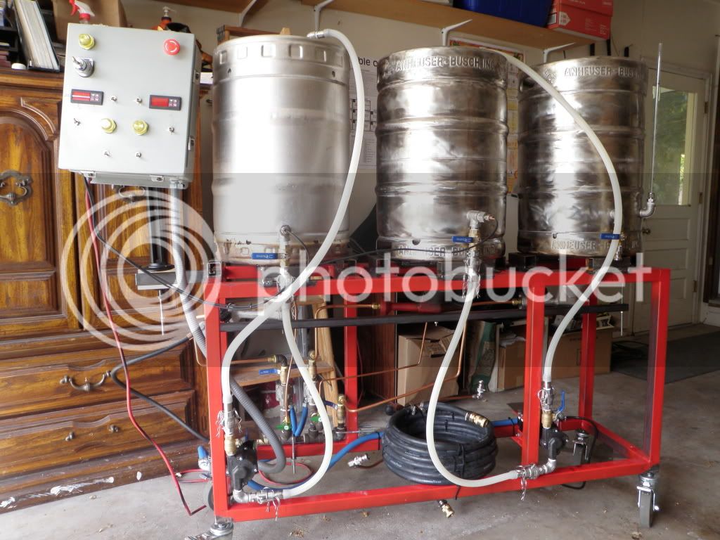
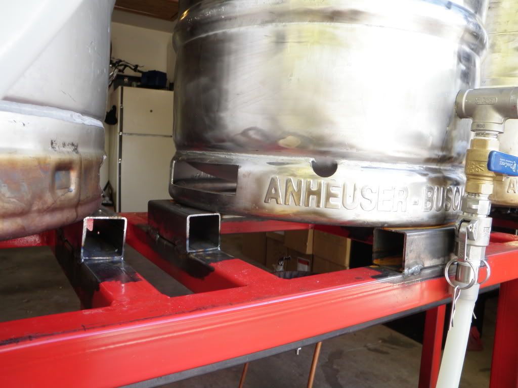
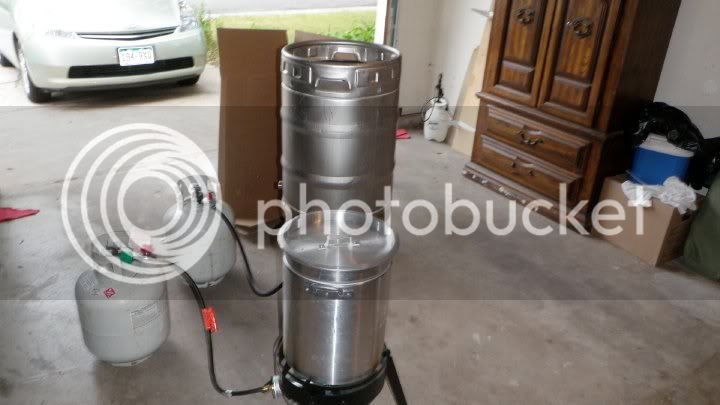
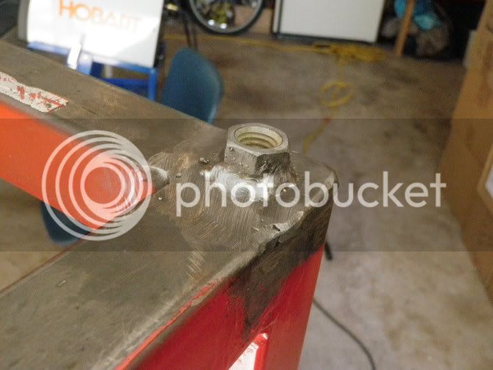
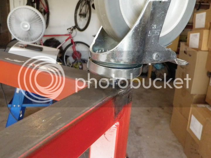
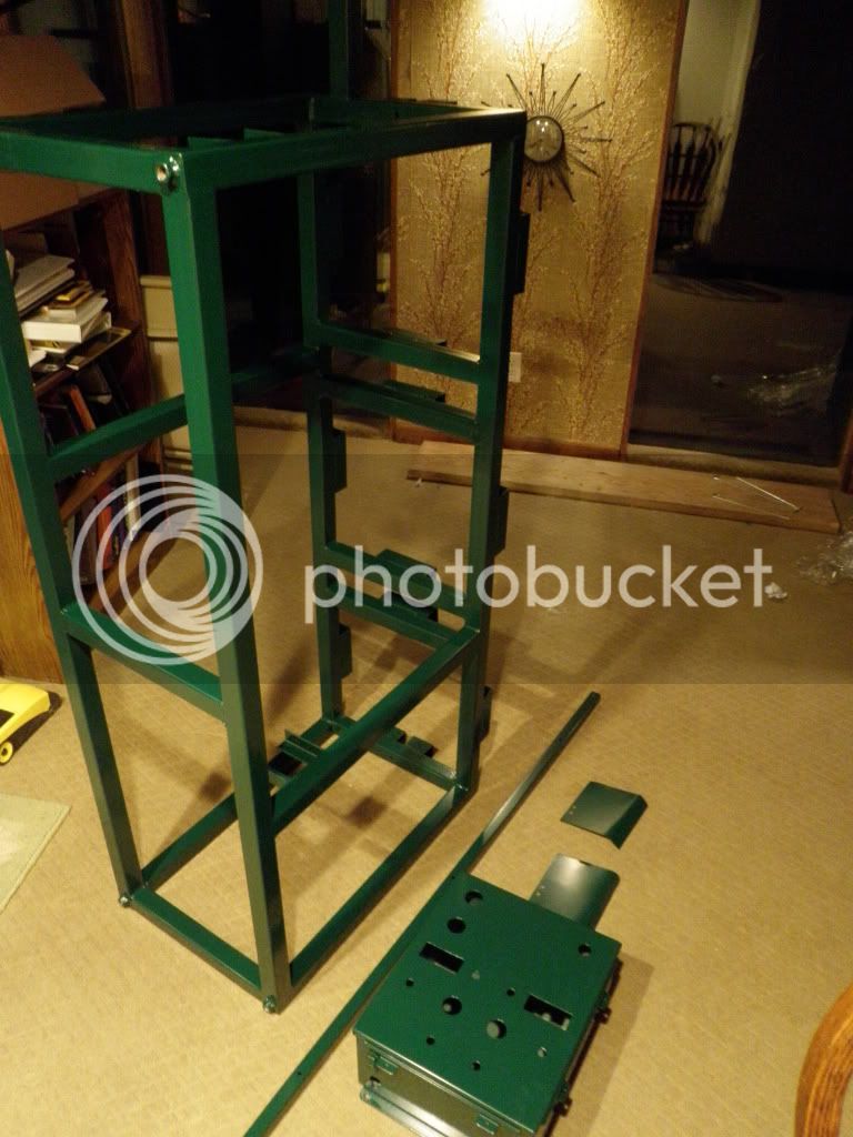
I increased the height of the stand from 20 to 26, PLUS I added those welded heat sink blocks. I didnt think of adding those until AFTER the stand was complete. Hindsights 20/20. However the top of the keggle is still below my armpit so, its all good. However, I would rather be able reach into the keg easier while its on the stand, but its nothing for me to cry about. :( I recommend keeping it at 20-22.
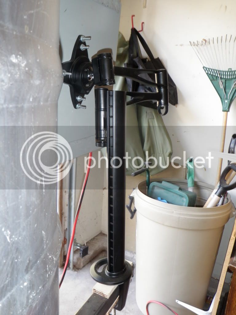
Dude, the control panel/monitor arm is a great idea. I may have to steal it for myself!
Thanks! Please, take my wife, too!
You can get it on eBay for about $40, and its so worth it, bro. I move that thing around a few times on brew day. I keep the clamp insulated with plywood, although I think now that its a little redundant. I love redundancy (obviously with my future upgrades
), though, so its all good.
why the heat sink blocks and the vent holes in the kegs?
Working with diatonic and snake10, I believe that if you want color on your stand, then you need some way of dissipating the heat off of the stand. The top of the stand still gets pretty hot even with those two things, so Im glad I chose to do them. I may even bolt on some huge, ****-off heat sinks on the back. I think theyll look cool.
FWIW, venting the keg skirt actually decreases the burner efficiency. I ran a test recently to verify this and it took approximately 30% longer to bring an equal volume of water to a boil from the same starting temperature with the vented skirt. I was expecting a significant improvement or, at worst, little or no gain. The tests indicated exactly the opposite. Time to boil was about 30 minutes without the vent and 40 minutes vented using six gallons of water at 80F.
Thank you for performing that test. I was wondering about that. Homebrewers are like mythbusters! I figured it would take a little longer, but its all good cuz now I dont have to worry about the paint bubblin or crackin or whatever.
Nice looking build! What are you using for lids?
Thanks, bro! I bought them from the Wok Shop on amazon. Theyre advertised as 16 but are actually 15. I knew that before buying them, and bought them anyway. I had to jury rig them to prevent them from falling into the keggle. I just used screws, lockwashers, and nuts. The screws stick out a bit to keep the lid on. You should be able to see one of them in the picture.