Slow PWM using hacked LED dimmer

Homebrew Talk - Beer, Wine, Mead, & Cider Brewing Discussion Forum

Help Support Homebrew Talk - Beer, Wine, Mead, & Cider Brewing Discussion Forum:

This site may earn a commission from merchant affiliate links, including eBay, Amazon, and others.

alien

Well-Known Member
Joined
Apr 27, 2012
Messages
1,234
Reaction score
70
Location
Philadelphia
Turn an inexpensive LED dimmer into a PWM timer for an electric element by swapping out a single capacitor:

Blog post: http://smokedprojects.blogspot.com/2013/09/led-dimmer-pwm-hack.html

pwm1.jpg
 
Don't try this one with a light dimmer from Lowes or Home Depot. They aren't rated for the current your element draws and they aren't PWM.
 
Exactly!

I have a spare so if anyone wants the 1.5 Hz PWM timer it is $10 shipped within the USA. Contact me via PM.
 
Good luck! Desoldering the original cap was the hard bit (for me anyway).

There is a lot of electronics in one of these little dimmers for $4 or however much they are.
 
Alien,

I received my two dimmers but the circuit board is different. I have watched that video and looked at your pics and think I found which capacitor to switch but thought I should ask you first. Is there a way to verify which I one using just a normal multimeter? If my phone can upload pics I'll attach one of the boards.
I think it's C4?


image-3432809859.jpg
 
I have a couple of spares knocking around. I opened them up and they are different again! The PCB is neither green nor blue, but maroon -- and all the components are very helpfully labelled part with numbers and values, as on yours.

One of the 8-pin chips should be marked NE555. Orient the chip so that the bar is at the top, and count the pins from the top left (1) to the bottom left (4) and back up the other side from the bottom right (5) to the top right (8). There might be a dot next to pin 1. The timing capacitor should be connected to pin 1 on one end (ground) and pins 2 and 6 on the other end. Some of the connections may be visible on the PCB, some may be underneath the chip and not visible.

On that basis it looks very much like C4 as you say, which has the same value that mine did (0.1uF), so swapping it for 47uF or 100uF should get you in the ballpark. Good luck! :)
 
Finally got around to trying this. My desoldering skills are quite lacking and I ended up just pulling the pads and everything off the board. I even thought there was some stray solder in the masking to I tried to pry it off, turned out it was some of the metal from the circuit, so I soldered the leg of the capacitor to pin 2 of the 555 chip and a bridge to the closest resister. :rolleyes:


Hooked it up to a SSR and a pencil sharpener motor. Everything seemed to work great. I could vary the pulse from off to full on. One thing I noticed is that when I first plugged it in, even if the pot was in the off position it would send one small pulse to the motor and then stop.

Thanks for this great little gem. Now I gotta find time to try it out for an element.

:rockin:

IMG_4050.jpg
 
With the lid on nobody will know. Actually I pulled one of the pads off mine and had to scratch away part of the mask to solder to the ground plane. :D
 
Hi!
Sorry for reviving the thread, but I have some info to add if someone else finds this later.
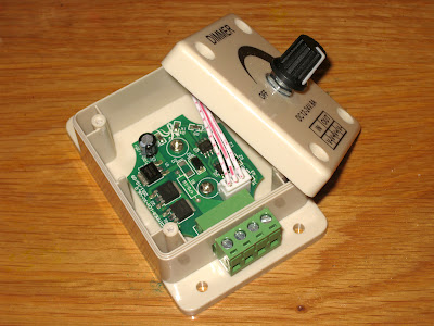
I found this thread (and magic's page) after I already reverse engineered a similar dimmer and modded it to SSR freq. for a cheapo RIMS system I'm planning.
I also found that a 100uf cap got me in th 1Hz range.
The tip I have is, if you want to decrease freq. by adding capacitance, you can avoid desoldering the smd cap and risk damaging the pcb. You can just solder the new cap in parallell. This makes it easy to undo later as well.
I just cut the legs of the electrolyte to appropriate length, pretinned, added some fresh solder to the pads and soldered it in.
Cheers!
 
Good idea!

Any chance of a picture? There are so many different versions of the board inside - might be useful to somebody!
 
Hmmm. No specs given on the potentiometer. I'd be wary unless the seller could provide more details.

To clarify: this listing is for an SSVR that operates by phase angle control not PWM. In this design, the pot has to handle mains voltage and should be rated for at least 2W.
 
Ok, snapped a pic.
The extra cap is in the upper left corner, marked c13.
2r6llzl.jpg


I totally agree regarding PWM + SSR vs SSVR, not that SSVR's don't have their place, but for the application this is better. No 'hot' pot, no electrical noise.
Cheers!
 
Gonna revive this. Thanks alpha, I still have another one lying around and I'm gonna try your method. I'm am doing a two panel setup with high voltage in one and low voltage in the other. It will have a manual mode using these and a raspberry pi for the auto mode.
 
I like separation of hv and lv. And I also like your approach to have a manual override that uses physical knobs.
These dimmers are awesome, my favorite piece of cheap electronics after the stc-1000 :) I hope it will serve you well!
Though, alien is the one you should thank, my contribution in this thread is neglectable :)
 
Yet another variation of the board, what do you think? The right side 8 pin chip is the 555 with the writing facing correctly in the pic

Thanks, Jim

image.jpg
 
It looks like it is just another layout of the same basic idea.
You cant tell from the picture which cap is the timing cap (I'd guess C4). You'd need to measure the connections. If putting in an electrolyte, you'd need to know polarity anyway.
 
Thanks. Now I just noticed the temp controller in your signature. I'm setting up a fermenting fridge, purchased a A419 stat by johnson controls, then I found the ITC-1000 which I believe t be the F version of the temp controller you have. The itc-1000 is 1/3 of the price and looks to do the exact same thing. How do you like yours?

It looks like it is just another layout of the same basic idea.
You cant tell from the picture which cap is the timing cap (I'd guess C4). You'd need to measure the connections. If putting in an electrolyte, you'd need to know polarity anyway.
 
@Traz1986: This is off topic for this thread, so I suggest asking in a more appropriate thread.
But as you asked, I'd like to point out that STC-1000+ is not a temperature controller per se (though it is targeted for the STC-1000 controller), but a firmware replacement (i.e. it is my pet project to build a software better suited for fermentation and brewing and stuff).

Cheers!
 
Back
Top