Looks great! Nothing like breaking in new brew equipment eh?
You are using an out of date browser. It may not display this or other websites correctly.
You should upgrade or use an alternative browser.
You should upgrade or use an alternative browser.
My two 5500 watt element 1 PID and SSR build
- Thread starter bigljd
- Start date

Help Support Homebrew Talk:
This site may earn a commission from merchant affiliate
links, including eBay, Amazon, and others.
OP
OP
bigljd
Well-Known Member
Looks great! Nothing like breaking in new brew equipment eh?
It was a fun day. One thing I did realize during the boil is that the storage shelf directly above the control panel funnels the steam from the kettle straight towards the panel, and water was condensing on it. I ended up moving the kettle out towards the middle of the shed so the steam could go up to the ceiling away from the panel. I was worried I'd short the whole system out on the first run, but it all worked out good.
It was kinda weird too, at how quiet it was during the boil. I'm used to the sound of the propane burner, and it was completely silent except for the bubbling wort.
I love my e-brewery!
Lamp24
Member
Thats a good looking system bigljd. Can I ask what is the reason for the contactors? I see some people are using them and others are not.
OP
OP
bigljd
Well-Known Member
Thats a good looking system bigljd. Can I ask what is the reason for the contactors? I see some people are using them and others are not.
Thanks - the contactors keep the element's full power load from going thru a switch. A switch controls a smaller 120v current - when the switch is turned on it powers the contactor coil which closes the contactor connection and allows the 240v 30 amp power to flow to the elements from the SSR.
30amps is a lot of power, and I just felt more comfortable having it controlled by contactors instead of a switch, but others have had success using switches. It's a personal choice.
OP
OP
bigljd
Well-Known Member
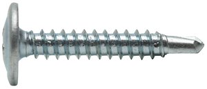
Nice build! Nice brewspace! I used a couple self-tapping screws to secure the heat sink. JB weld is liquid duct tape...it has it's place.
Tonight I drilled two 9/64" holes through the top of the enclosure on both sides of the SSR, penetrating through the first level of the heat sink. Then I screwed #8 - 3/4" self tapping screws through the holes, and the heat sink is locked down nice and tight to the enclosure. Total cost, $0.98 for the screws from Lowes. I finished it off with a bead of clear silicone caulk around the heat sink to keep any water out in case I do something silly like spray my panel with a hose.
I've got some vinyl decals coming from Bobby to label all the switches and make it look good - then it will be finished! I'll do a final picture show of the entire setup.
If I can awaken from my Thanksgiving turkey coma I'll brew a batch on the completed system on Friday, and I'll get to put the new e-keggle HLT thru it's paces.
Glad you got it done. Self tappers are awesome. I always have some around. These for thicker metal:
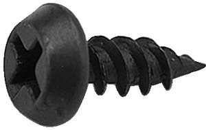
And these are great for plastic and sheet metal:
I am going to try to brew on Friday too. Cranberry Wheat for Christmas I think.
And these are great for plastic and sheet metal:
I am going to try to brew on Friday too. Cranberry Wheat for Christmas I think.


$7.79 ($7.79 / Count)
Craft A Brew - LalBrew Voss™ - Kveik Ale Yeast - For Craft Lagers - Ingredients for Home Brewing - Beer Making Supplies - (1 Pack)
Craft a Brew


$53.24
1pc Hose Barb/MFL 1.5" Tri Clamp to Ball Lock Post Liquid Gas Homebrew Kegging Fermentation Parts Brewer Hardware SUS304(Liquid MFL)
yunchengshiyanhuqucuichendianzishangwuyouxiangongsi


$10.99 ($31.16 / Ounce)
Hornindal Kveik Yeast for Homebrewing - Mead, Cider, Wine, Beer - 10g Packet - Saccharomyces Cerevisiae - Sold by Shadowhive.com
Shadowhive


$53.24
1pc Hose Barb/MFL 1.5" Tri Clamp to Ball Lock Post Liquid Gas Homebrew Kegging Fermentation Parts Brewer Hardware SUS304(Liquid Hose Barb)
Guangshui Weilu You Trading Co., Ltd


$33.99 ($17.00 / Count)
$41.99 ($21.00 / Count)
2 Pack 1 Gallon Large Fermentation Jars with 3 Airlocks and 2 SCREW Lids(100% Airtight Heavy Duty Lid w Silicone) - Wide Mouth Glass Jars w Scale Mark - Pickle Jars for Sauerkraut, Sourdough Starter
Qianfenie Direct


$22.00 ($623.23 / Ounce)
AMZLMPKNTW Ball Lock Sample Faucet 30cm Reinforced Silicone Hose Secondary Fermentation Homebrew Kegging joyful
无为中南商贸有限公司


$176.97
1pc Commercial Keg Manifold 2" Tri Clamp,Ball Lock Tapping Head,Pressure Gauge/Adjustable PRV for Kegging,Fermentation Control
hanhanbaihuoxiaoshoudian


![Craft A Brew - Safale BE-256 Yeast - Fermentis - Belgian Ale Dry Yeast - For Belgian & Strong Ales - Ingredients for Home Brewing - Beer Making Supplies - [3 Pack]](https://m.media-amazon.com/images/I/51bcKEwQmWL._SL500_.jpg)


$58.16
HUIZHUGS Brewing Equipment Keg Ball Lock Faucet 30cm Reinforced Silicone Hose Secondary Fermentation Homebrew Kegging Brewing Equipment
xiangshuizhenzhanglingfengshop


$28.98
Five Star - 6022b_ - Star San - 32 Ounce - High Foaming Sanitizer
Great Fermentations of Indiana

I was thinking about ordering them from you Bobby, and did visit your site a few times, but I'm probably going to just use the label maker I bought from Sprawlmart a while back. I'm just waiting until my wife has a chance to help me with it because I can never peel off the backing from the adhesive labels. She has longer nails so it's easier for her.
Well, you'll have the decals today or tomorrow.. no excuses let's see the pics!!
OP
OP
bigljd
Well-Known Member
Glad you got it done. Self tappers are awesome. I always have some around. These for thicker metal:
I am going to try to brew on Friday too. Cranberry Wheat for Christmas I think.
That's the screws I used - they worked great.
I'm getting all crazy and doing my first lager along with my first attempt at decoction mashing. I watched BruKaiser's YouTube video and am copying that. I've got all day to kill since my wife works but I'm off. The recipe will be for a Helles - we'll see how badly I can mess this up...
Well, you'll have the decals today or tomorrow.. no excuses let's see the pics!!
Cool, I've been looking for them in the mail this week. I'll shoot some pictures on Friday so I can do it during my brew session.
Thanks for sharing your build, I'm making a similar control box. I looked on elecdirect for the e-stop hardware and 240v indicator LED and couldn't find them. Mind sharing the part numbers? Thanks. Look forward to hearing how your brew goes tomorrow.
OP
OP
bigljd
Well-Known Member
Thanks for sharing your build, I'm making a similar control box. I looked on elecdirect for the e-stop hardware and 240v indicator LED and couldn't find them. Mind sharing the part numbers? Thanks. Look forward to hearing how your brew goes tomorrow.
It comes in separate pieces, but here are the links. Thanks to Ishiavo for sharing this - it came from his parts list.
Estop Parts:
MUSHROOM HEAD SPRING RETURN ACTUATOR METAL RED
COLLAR & 1 NO/1 NC CONTACT BLOCK Use the normally open side to the contact block if you are doing the GFCI e stop
ROUND LEGEND PLATE, 60MM DIAMETER, PLASTIC, EMERGENCY STOP
LED parts:
BODY, INTEGRAL CIRCUIT & CLUSTER LED RED 240V AC
HEAD, RED, HIGH CONTRAST FOR USE WITH NEON OR LEDs
I may as well put the toggles here too:
2-SCREWS, ON/OFF, CHROME HANDLE, MEDIUM DUTY
RUBBER BOOT [CLOSED]
and the power distribution blocks:
LINE 2/0-14AWG 1 OPENING, LOAD 4-14AWG 4 OPENING, 1POLE
Have fun!
OP
OP
bigljd
Well-Known Member
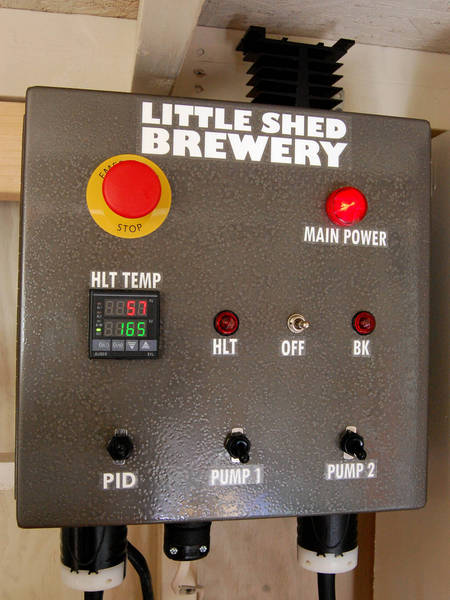
OK folks, here's the grand finale of this build. I got the vinyl panel decals from Bobby yesterday, so this morning I stuck them on and took some pics!
The completed control panel - there's some funky reflections going on in this picture, but the panel looks really good up close.
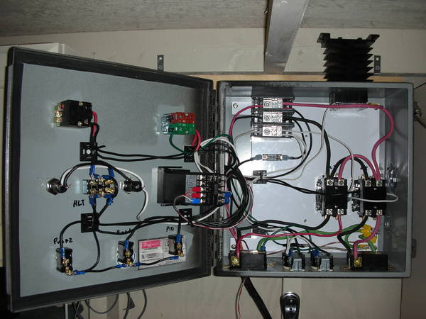
The guts of the panel:
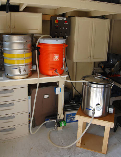
The finished brewery:
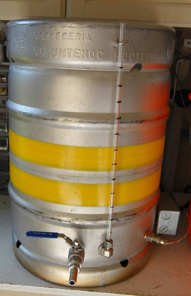
eKeggle HLT:
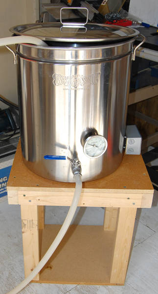
The kettle stand I built from some spare MDF and 2x3s I had lying around:
The receptacle wired into a 30amp 2 pole breaker in the home's main panel:
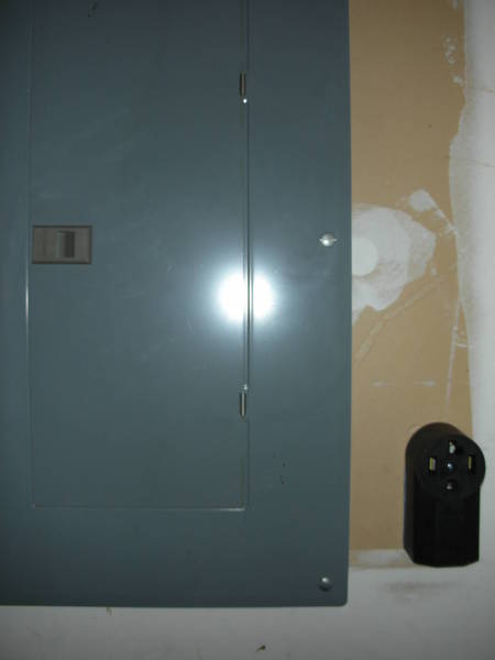
Utility room where the main breaker panel lives, with my brew shed in the background:

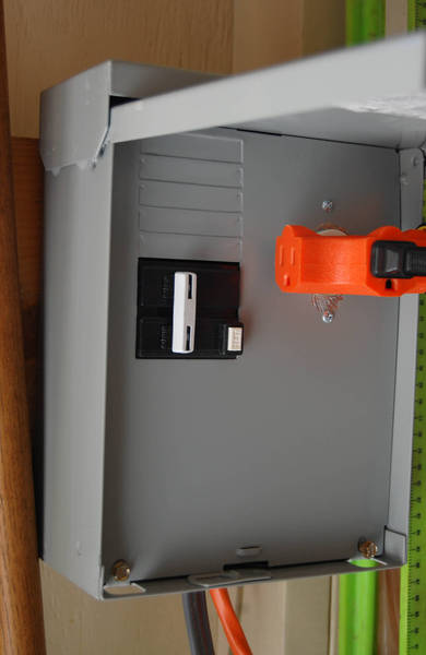
The spa panel mounted in the shed which provides GFCI protection to the system. I also mounted a 120v outlet that I wired to the panel with an inline 10 amp fuse. I use it to plug in a light for night brewing and to power the drill I use with my barley crusher:
Another view of the brewery:

I brewed my first German style lager yesterday and used the e-brewery to heat water and boil with, but used my propane burner to do a decoction with. It turned out well even though I botched the decoction volume and had to do another decoction to get the mash to the correct sacch temp.
I want to add the HERMs coil in the future to be able to do step mashes, hold temps more evenly during the mash, and possibly upgrade the MLT to a 15 gal size to do larger 10 gal IPAs. But for now I love my new setup! Electric brewing is so easy to use - just flip a couple switches and push a button and your water is heated for you and your boil holds steady for as long as you like!
Happy brewing
The completed control panel - there's some funky reflections going on in this picture, but the panel looks really good up close.
The guts of the panel:
The finished brewery:
eKeggle HLT:
The kettle stand I built from some spare MDF and 2x3s I had lying around:
The receptacle wired into a 30amp 2 pole breaker in the home's main panel:
Utility room where the main breaker panel lives, with my brew shed in the background:
The spa panel mounted in the shed which provides GFCI protection to the system. I also mounted a 120v outlet that I wired to the panel with an inline 10 amp fuse. I use it to plug in a light for night brewing and to power the drill I use with my barley crusher:
Another view of the brewery:
I brewed my first German style lager yesterday and used the e-brewery to heat water and boil with, but used my propane burner to do a decoction with. It turned out well even though I botched the decoction volume and had to do another decoction to get the mash to the correct sacch temp.
I want to add the HERMs coil in the future to be able to do step mashes, hold temps more evenly during the mash, and possibly upgrade the MLT to a 15 gal size to do larger 10 gal IPAs. But for now I love my new setup! Electric brewing is so easy to use - just flip a couple switches and push a button and your water is heated for you and your boil holds steady for as long as you like!
Happy brewing
Few more questions, I like your build and have the parts on order:
1) Are the resistors soldered in series and heat shrinked?
2) How did you splice off the ground from the spa panel? I see the two hots and neutral go to the blocks, but the ground goes off to the lower left portion of the box
3) What gauge wiring did you use in the control box. I see 10 gauge for the heating elements (contactors), but what about the rest of the wiring?
OP
OP
bigljd
Well-Known Member
I might have missed it in the thread somewhere, how do you control the 60 minute boil with a e brew setup.
When I've sparged enough wort to cover the heating element in the kettle, I flip the switch on the panel to the boil kettle side (BK). Then I switch the PID controller to manual mode and set it to 100% power until I reach a boil. Then I'll dial it back to 50 or 60% for the remainder of the boil and it holds a nice steady rolling boil for 60-90 minutes.
The same PID controller is used for both the HLT and BK.
Few more questions, I like your build and have the parts on order:
1) Are the resistors soldered in series and heat shrinked?
2) How did you splice off the ground from the spa panel? I see the two hots and neutral go to the blocks, but the ground goes off to the lower left portion of the box
3) What gauge wiring did you use in the control box. I see 10 gauge for the heating elements (contactors), but what about the rest of the wiring?
1. Yes, I soldered the 4 resistors in series, and on 1 end of the chain I soldered a ring connector, and on the other I soldered the wire that runs to the E-stop switch. Then I heat shrinked the resistors. You can sort of see them in the picture running along the bottom of the panel behind the 120v receptacles to the ground post.
2. The ground actually runs to the bottom right corner of the box, and all of the receptacle grounds and the control panel ground are joined on a ground post, which is just a bolt runs up through the back plate of the panel. The grounds are crimped to ring connectors and a nut secures them to the bolt. Kal does a much better job of showing it here:
Control Panel (Part 2)
3. The wire carrying the element load is 10g, but all the other wire is 14g and is protected by a 10 amp fuse (which is way more than the PID and pumps will every use). The only exception is the wire from the PID to SSR - the SYL-2352 PID only outputs 12 volts DC at 30mA so I used some wire cut from an old cell phone charger for the PID to SSR connection.
OP
OP
bigljd
Well-Known Member
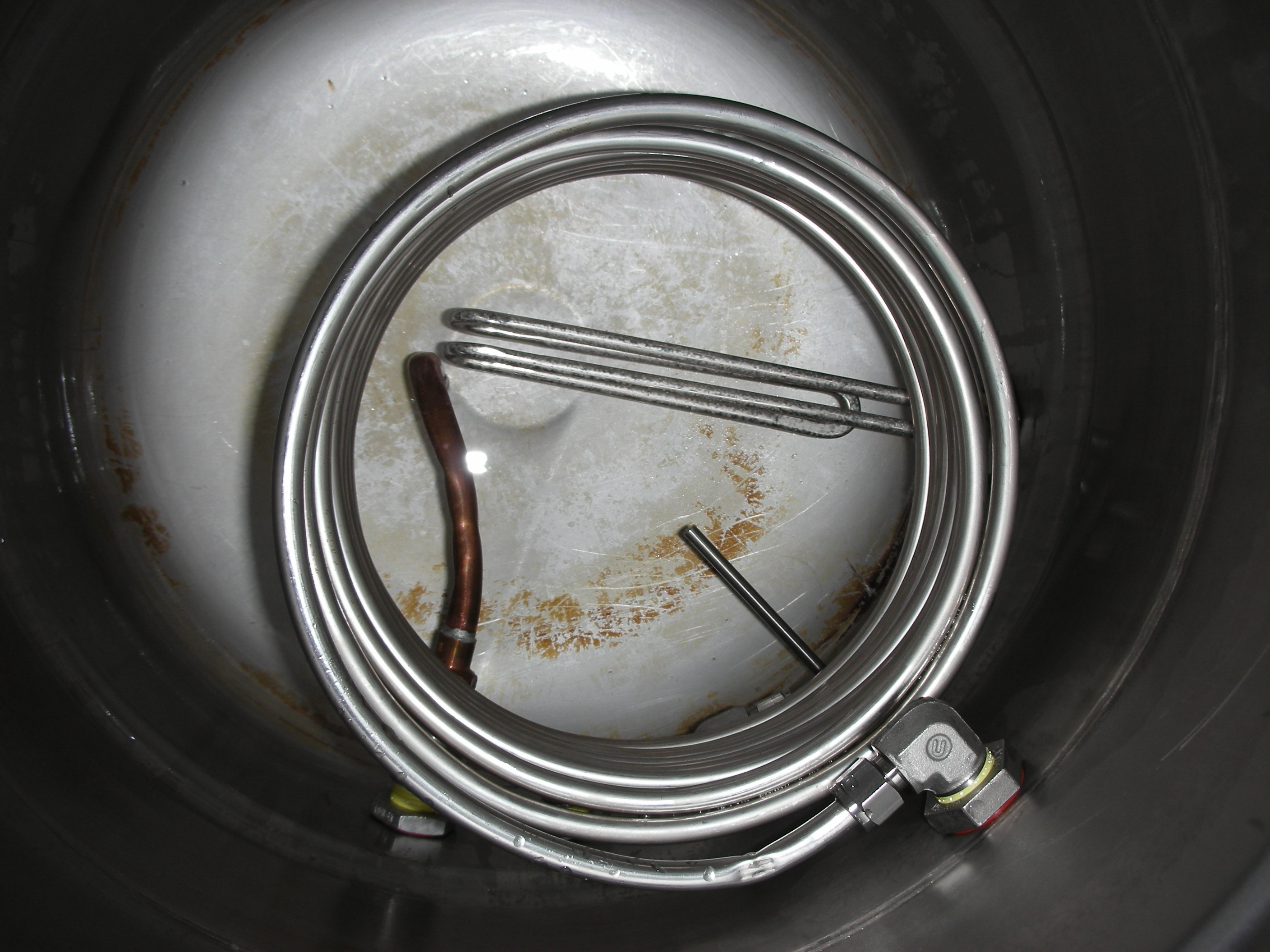
OK, so I thought I would update this thread with some upgrades I've done since finishing my original e-brewery build. The first addition was a HERMs coil I built into the HLT keggle. I used the SS coil from a spare 25' immersion chiller I had bought from NY Homebrew supply and SS parts from Bargain Fittings.com. I accidentally kinked one section of the coil, but was able to fix it. The HERMs works great.
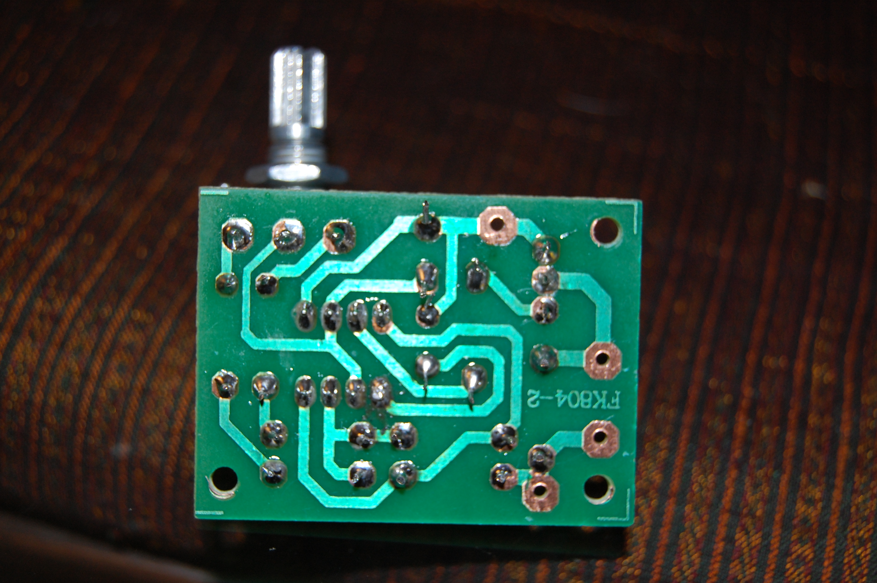
This week I built a PWM circuit from Bakatronics following the instructions in this thread. Here's the circuit:


Then I built it into my control panel. I needed a 12 volt power supply and a 4 pole double throw switch for the PWM circuit, both of which I found for pretty cheap at AllElectronics.com.
I have 1 pole of the 4 pole element selector switch controlling 120VAC to the contactors, 1 pole turning on the indicator lights, and 2 poles switching the 12VDC legs between the PWM circuit and the PID controller, so that the SSR is run by the PID when switched to the HLT, and the SSR is run by the PWM circuit when switched to the BK.
Here's how it looks in the panel - the PWM knob is on the top row between the E-stop and the power LED:

I mounted the 12VDC power supply to the top inside of the enclosure using a big piece of adhesive velcro. Here's the guts of the panel:

I've done some testing with it with only 120VAC wired into the panel just to test the PWM circuit and the new switch. Everything seems to work great - the SSR LED barely blinks at all when the PWM circuit knob is turned to Lo, and is on about 98% of the time when the knob is cranked to Hi.
I won't do a full power test for a while though, since I've shut down the brewery for the summer. I've got too much beer to drink, and it's too hot to make more.
Cheers!
This week I built a PWM circuit from Bakatronics following the instructions in this thread. Here's the circuit:
Then I built it into my control panel. I needed a 12 volt power supply and a 4 pole double throw switch for the PWM circuit, both of which I found for pretty cheap at AllElectronics.com.
I have 1 pole of the 4 pole element selector switch controlling 120VAC to the contactors, 1 pole turning on the indicator lights, and 2 poles switching the 12VDC legs between the PWM circuit and the PID controller, so that the SSR is run by the PID when switched to the HLT, and the SSR is run by the PWM circuit when switched to the BK.
Here's how it looks in the panel - the PWM knob is on the top row between the E-stop and the power LED:
I mounted the 12VDC power supply to the top inside of the enclosure using a big piece of adhesive velcro. Here's the guts of the panel:
I've done some testing with it with only 120VAC wired into the panel just to test the PWM circuit and the new switch. Everything seems to work great - the SSR LED barely blinks at all when the PWM circuit knob is turned to Lo, and is on about 98% of the time when the knob is cranked to Hi.
I won't do a full power test for a while though, since I've shut down the brewery for the summer. I've got too much beer to drink, and it's too hot to make more.
Cheers!
lunchbox
Well-Known Member
I really like your setup. Is the BK dimmer switch used to control the amount of power the heating element uses?
OP
OP
bigljd
Well-Known Member
Yes, the BK Control knob is actually a PWM circuit that controls how much power goes to the boil kettle heating element. When set all the way on Lo, the BK element will only be at about 5% power. When all the way on Hi it will be at about 95% power. You can hold a good rolling boil at about 50-65% for 5-10 gals of wort. The PID controller is being used only for maintaining water temps in the HLT, and the PWM circuit controls the kettle element.
In all honesty, the PWM circuit was not necessary. The Auber PID has a manual mode on it that you can use to control the boil pretty much the same as the PWM circuit does. I just thought it would be a cool project to build a PWM, and after I built it I decided to add it to the control panel. I was having to fiddle with some of the settings with the PID controller to get a smooth boil in the kettle each brew, so that is part of the reason I added the PWM, but it wasn't really necessary. The optimum PID settings to maintain water temps in the HLT are not always the optimum settings to boil wort in the kettle. So now I have separate controller for each.
EDIT: I see you are in Charlotte - if you are looking to upgrade to electric and want to check out my rig, let me know. I'm not far away in Indian Trail.
Awesome. This would be an interesting project.
Do you have any specs for boil times? Say from room temperature to full boil in X minutes for X volume of water. Say X minutes for X gallons of water from X temperature?
Saw you listed 63 to 150 in 21, but i was just curious how much longer it takes to get from that temp to full boil.
Do you have any specs for boil times? Say from room temperature to full boil in X minutes for X volume of water. Say X minutes for X gallons of water from X temperature?
Saw you listed 63 to 150 in 21, but i was just curious how much longer it takes to get from that temp to full boil.
lunchbox
Well-Known Member
bigljd, I'd love to check out your rig. It's a bit overwhelming to jump into electric when you have little to no experience with that type of stuff.
OP
OP
bigljd
Well-Known Member
There is a formula in the middle of the page below from Kal that gives you theoretical heating times for electric water heating. That might help you. I think 10 gals at 70 degrees taken to a full boil would take about an hour. I just know that I can heat about 10-11 gal to strike temp in about the same amount of time it takes to crush my grain and get my other stuff ready for the brew day. While I'm sparging I'll start slowly heating the wort in the kettle once the wort level is comfortably above the element (element at about 65-70%), so that my wort is almost to a boil by the time my sparge is done. When my sparge is finished I may have to give it full power for a few minutes and I'll be at a rolling boil.
http://www.theelectricbrewery.com/forum/viewtopic.php?p=284087
_
http://www.theelectricbrewery.com/forum/viewtopic.php?p=284087
_
OP
OP
bigljd
Well-Known Member
bigljd, I'd love to check out your rig. It's a bit overwhelming to jump into electric when you have little to no experience with that type of stuff.
Funny, I completely missed your post here since I was replying to another post at the same time you posted this. I'll send you a PM with my address, and you can check it out sometime (or I'm brewing Saturday am, so you can see it in action then too).
BuddhaNole
Member
- Joined
- Jan 21, 2015
- Messages
- 16
- Reaction score
- 2
I'd like to start off by saying thanks so much for this thread. I am in the last few steps putting this exact set up together and I could not have done it without all of this great info. I did have one question regarding this statement.
This makes it sound as if the 1 amp fuse and resistors are between the E-Stop and the ground. But the wiring diagram on the first page show the fuse and resistors between the load and the E-Stop button. Can someone confirm for me which way it should be? Thanks in advance.1. Yes, I soldered the 4 resistors in series, and on 1 end of the chain I soldered a ring connector, and on the other I soldered the wire that runs to the E-stop switch. Then I heat shrinked the resistors. You can sort of see them in the picture running along the bottom of the panel behind the 120v receptacles to the ground post.
OP
OP
bigljd
Well-Known Member
I'd like to start off by saying thanks so much for this thread. I am in the last few steps putting this exact set up together and I could not have done it without all of this great info. I did have one question regarding this statement.
This makes it sound as if the 1 amp fuse and resistors are between the E-Stop and the ground. But the wiring diagram on the first page show the fuse and resistors between the load and the E-Stop button. Can someone confirm for me which way it should be? Thanks in advance.
Hi - The diagram does show the resistors before e-stop button, but I did wire in the resistors after the button. I did not use the 1 amp fuse, after having a discussion it was determined that the fuse was not needed, since if the fuse failed then the e-stop circuit would fail. Ideally I'd say to have the resistors before the e-stop button, but the circuit will work fine if you place them after. The point of the resistors is to limit the load that gets sent to the GFCI breaker when the e-stop button is pushed. Only a small current is needed to trip the GFCI. The resistors will limit the load if they are before or after the button.
EDIT: If you do have the resistors before the e-stop button, be sure to shield the soldered connections well, since they will be carrying a load 100% of the time that the panel is powered up. If you have the resistors after the button, they should still be shielded well, but will only carry a load for a brief moment after the button is pushed and before the GFCI trips.
BuddhaNole
Member
- Joined
- Jan 21, 2015
- Messages
- 16
- Reaction score
- 2
That's sort of what I thought, but I'm no electrician. Thanks so much for your help bigljd.
Similar threads
- Replies
- 20
- Views
- 1K
- Replies
- 37
- Views
- 3K
- Replies
- 14
- Views
- 3K
