Help with relay wiring for safe start interlock

Homebrew Talk - Beer, Wine, Mead, & Cider Brewing Discussion Forum

Help Support Homebrew Talk - Beer, Wine, Mead, & Cider Brewing Discussion Forum:

This site may earn a commission from merchant affiliate links, including eBay, Amazon, and others.

cheez

Well-Known Member
Joined
Aug 25, 2010
Messages
178
Reaction score
7
Location
Green Side of
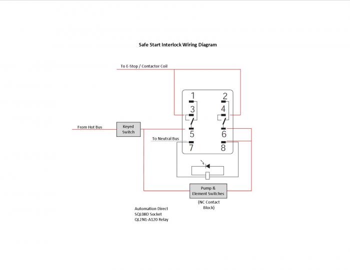
I need help wiring this relay I got from Automation Direct. It did not come with any instructions other than a basic wiring diagram. I tried to reference it to other relays that others have used but I want to make sure it's right before sending 110 volts of juice through it.

This is the last part of wiring in the panel that I need to do (see overall build thread here: https://www.homebrewtalk.com/f170/e-herms-build-50-amp-393717/)

I've attached a jpg of the relay wiring along with a PDF link of the overall wiring diagram.

Thanks for any help.

Safe Start Interlock Wiring Diagram.jpg


View attachment Wiring Diagram 4.pdf
 
I took a quick look at the diagrams but I'm at work so I don't have time to dive in to much. Looks like the diagrams give you the info you need. Its just a control ckt to a mushroom all stop button. The power leads should wire into an aux relay that is on your main supply breaker. If you still need help I can look into it a bit more after work. Sorry I know this isn't exatcly the perfect reply.
 
Thanks for the response. I should have clarified... I know how to "generally" wire up the relay as far as I know where it goes and what it is supposed to do. I am just not certain if I have the correct wires going to the correct terminals on the relay itself.
 
Ha ha. Bummed out. I just typed it all up and then messed up and erased it all, so I will try again.

Sorry for the delay, but I work long days right now so finding time to do stuff like this is sparse.

Tracing out the circuit you are taking a control leg from one of the 120v phases and bringing it to the keyed switch, then from the keyed switch to point 5 on the interlock. This is your main control point, if the key is on but the mushroom button is pushed in, the lights will light up saying its on, but nothing will work.

The wire that taps off the other side of the keyed switch starts your control circuit, runs through all your devices, and ends up back on the interlock points 8 and 6. So point eight just brings power to the interlocks relay telling it to turn everything on, and the grey wire from points 7 to 8 with the diode in parallel with it should be factory wired.

Point 7 on the interlock is simply your return, so it is one wire going to your neutral bus.

From point 5 to 1 is a NC contact and so is 6 to 2.

From point 5 to 3 is a NO contact, and so is 6 to 4. Points 3 and 4 are both what you bring back to your E-Stop, and ultimately your A2 point on the AUX Relay on the main Contactor. That is the full control circuit where the interlock is involved.

Essentially you are creating a logic circuit saying "If the key is on, but the E-stop is off, turn your lights on but with no operability. If the key is on and the E-stop is on, then everything is on with operability. If the key is off at all, or both are off then nothing is on at all."

After tracing it all out I'm a little confounded though. I don't think you actually needed the interlock at all. You might as well use it, but you could have wired it all the same where the keyed switch goes through the control circuit and to the E-stop. That would have provided the same results since the NC circuits are not used at all.

Good luck dude. Once again sorry for the late reply, but hopefully good brewing is afoot with your setup.

Wow! Thanks for taking the time for that response. Just to double check, the wiring diagram I made for the relay is correct?? I didn't know if it mattered if the key went to 5, switches, and to 6/8 or if it was supposed to be key to 6 to switches to 5/7.

I think I see what you are saying about doing away with the relay if I put NC blocks on the switches that I wanted to be on my "safe start" system. I am going to look at this again... Thanks again.
 
After looking at my overall wiring diagram, it does look like I could simply remove the "Safe Start Inerlock", keep the key switch and E-stop where I have them, and simply wire NC blocks on the pump and element switches between the key and e-stop. This is simple since I already have the NC blocks installed as part of the original setup. I just hadn't installed the relay yet.

If any of these switches are engaged, the NC block would be open and would not allow power to flow from the key switch through the e-stop to the main contactor that turns all of the power on. Assuming this is all correct (it seems right in my pea brain), I don't know why I didn't see it before! This will save me a few feet of wire and I can do away with a relay.

If this is correct, why do so many people have a "safe start" relay? I feel like I am missing something.
 
I just went through the logical circuit from what you had posted. It looks like a vendor supplied diagram of connections.

Basically the interlock is like having two switches operated at the exact same time, operated from the relay. So point 5 goes to both point 1, and point 3. In this case when there is no power supplied to the relay then point 1 and 5 are closed creating one circuit. If the relay is energized the contacts change state closing points 1 and 3 and opening 1 and 5.

The exact same thing happens with the opposite side of the interlock and points 6, 2, and 4.

The typical use of this item is switching from a main power supply, such as the grid; to reserve power , such as a generator, in the event of total loss of power. In a typical use that I would see, the circuit would be exactly the same minus the key switch and the E-stop. The main power would goto the NO contacts 4 and 3, and the backup power would goto the NC points 1 and 2. Then 5 and 6 would goto a panel or whatever you are supplying with power. The relay would use a leg of 120v from the main power, so if the main supply of power is on then the relay is kicked on, but if you lose power it automatically transfers to reserve power making it impossible to mix of sources.

Either way, I'm pretty sure from your replies that you have the gist of what needs to happen to wire this thing, and should be able to do so confidently.

Also from your second post about removing the interlock, yes I'm almost certain your correct. Only almost certain because I'm not there helping you out and looking at how everything is actually done.

Here's an updated wiring diagram. I am assuming that once the 63a contactor is energized, it stays that way until the key switch is turned off. If that is the case, I do not see why NC blocks on the pump and element switches would't work for a safe start setup. If any of the pump or element switches are on, the circuit cannot be completed between the key switch and main contactor when the key switch is first turned on.

Worse case is that I will find out in a couple of weeks when I turn it on for the first time.

View attachment Wiring Diagram 3.pdf
 
Loos great to me. I did one more run through of your diagram and it makes sense.

orangehero made a good point on my main build thread that as soon as I turn one of my pump or element switches on, the NC block will cut power to the main contactor, effectively cutting power beyond the contactor.

So... it sounds like I still need the relay.

When I look at the relay wiring diagram, I see power coming into terminal #5 from the key switch and power going into terminal #6/8 (assuming the pump/element switches are not engaged). Wouldn't the power going to #5 engage the main contactor regardless of what's going on with the pump/element switches? How to the two internal switches on this relay work? I'm usually not too easily confused but this one has me going in circles...
 
I can see why you are going in circles because yes you are right about terminal 5 and that was one thing that was confusing me is it is a big circle. It makes sense because That point would supply power to your main relay reguardless of what anything else is doing in your control circuit.
 
One more thing though, wouldn't you bring one wire in, and one wire out to each switch on each of the contacts to jump your power through each device in the circuit but not have the power interrupted by a singular device as what you just described?

Just asking cause your diagram I looked at showes all the devices but not necessarily what the wire is going to speciffically. So I couldn't tell if its the NC contact or just a power point.

Maybe I can tell but there would be some guessing going on.
 
Oi. One more thing I feel the necessity to say. I was going to on a previous post but negelected to do so untiol now. You made another wiring diagram removing the interlock. On that one if you did the wiring that way but also added a second wire from the load side of the key switch to the line side of the e-stop it would also solve your problem.

You would basically have two wires coming from the key switch, one to the e-stop and one to the 120 illum switch (hlt)

I'm sorry I should have mentioned that but at the time I didn't think it was a necessary wire
 
What are you trying to achieve with this safe start interlock? I've got one in mine, but it doesn't tie into the EPO. It works perfectly, and the same way Kal designed his - panel won't turn on unless the pump and heating element switches are normal. The EPO circuit is totally separate, so I'm a little confused with what your actual endstate is with this setup of yours.

-Kevin

The safe start interlock would prevent me from being able to turn on the panel with the key switch when any pump or element switch is on.

Instead of having the EPO send juice down a ground wire to trip a gfci, my EPO stops the current going through the main contactor. Obviously this woudln't kill power TO the panel but would kill it inside the panel. I think it's a no-no in the electrical world to send power down a ground wire. Although, I'm sure there are some other no-no's going on inside these panels :) My EPO could probably be placed between the key switch and safe start relay as well. It just needs to go between the key switch and contactor.
 
I found your herms thread and didn't realize the full scope of what was going on. I didn't realize that there were nc contacts running in series through everything until I had posted everything.

I just wanted to apologize if I got you going in the wrong direction.

I can say that with everything the way it is your setup should work no problem after looking at everything again.

That's cool. I still appreciate you took the time to help :mug:
 
I do have one question for ya. Do you know if the interlock is mechanically latching or an electrically held latch.

Dunno. I listed the automation direct model # on the diagram. Someone else on this forum has the same relay but for the life of me I cannot find them.

Edit: Here's the relay and socket I have http://www.automationdirect.com/adc/Shopping/Catalog/Relays_-z-_Timers/Electro-Mechanical_Relays/Square_-z-_Cube_Relays,_Plug-In,_3A_-_15A_(78x-z-_Qxx-z-H78x_Series)/General_Purpose,_3A,_5A,_10A_(QL2_-z-_QL4_-z-_QM2_-z-_QM4_Series)/QL2N1-A120

http://www.automationdirect.com/adc/Shopping/Catalog/Relays_-z-_Timers/Relay_Sockets_-a-_Accessories/Relay_Sockets/SQL08D and below are the specs. They say it is "electromechanical" whatever that means.

View attachment qlrelays[1].pdf
 
Awesome Cheez. Thanks for taking the time to update this and letting us know this works. I am so going to use this in my panel.
 
Subbed, trying to figure out my eBIAB control panel with Eaton M22 pushbuttons and all types of safety features. Anyone know how to find "seal-in coil relays" or ones that only require a momentary switch be pushed once to close the coil, but if power loss occurs they do not remain in the closed position?
 
Subbed, trying to figure out my eBIAB control panel with Eaton M22 pushbuttons and all types of safety features. Anyone know how to find "seal-in coil relays" or ones that only require a momentary switch be pushed once to close the coil, but if power loss occurs they do not remain in the closed position?

What you're trying to do could be done fairly easily with a standard NO relay - use the momentary to power the coil and close the switch. Run a jumper from the load side of the relay to the coil. Once the coil is closed (with the momentary switch), it will stay closed as it is back-feeding power to itself via the jumper. On power loss, the relay reverts back to NO status, and the circuit is broken.

Of course, the above setup doesn't actually allow you to turn the relay off without somehow interrupting the power supply to the line side of the relay, unless you put a momentary NC switch in the jumper between the load and the coil.

-Kevin
 
Back
Top