Wire Gauge Question

Homebrew Talk - Beer, Wine, Mead, & Cider Brewing Discussion Forum

Help Support Homebrew Talk - Beer, Wine, Mead, & Cider Brewing Discussion Forum:

This site may earn a commission from merchant affiliate links, including eBay, Amazon, and others.

Brian Parfitt

Active Member
Joined
Apr 17, 2020
Messages
42
Reaction score
3
Quick question regarding wire gauge used in panels.

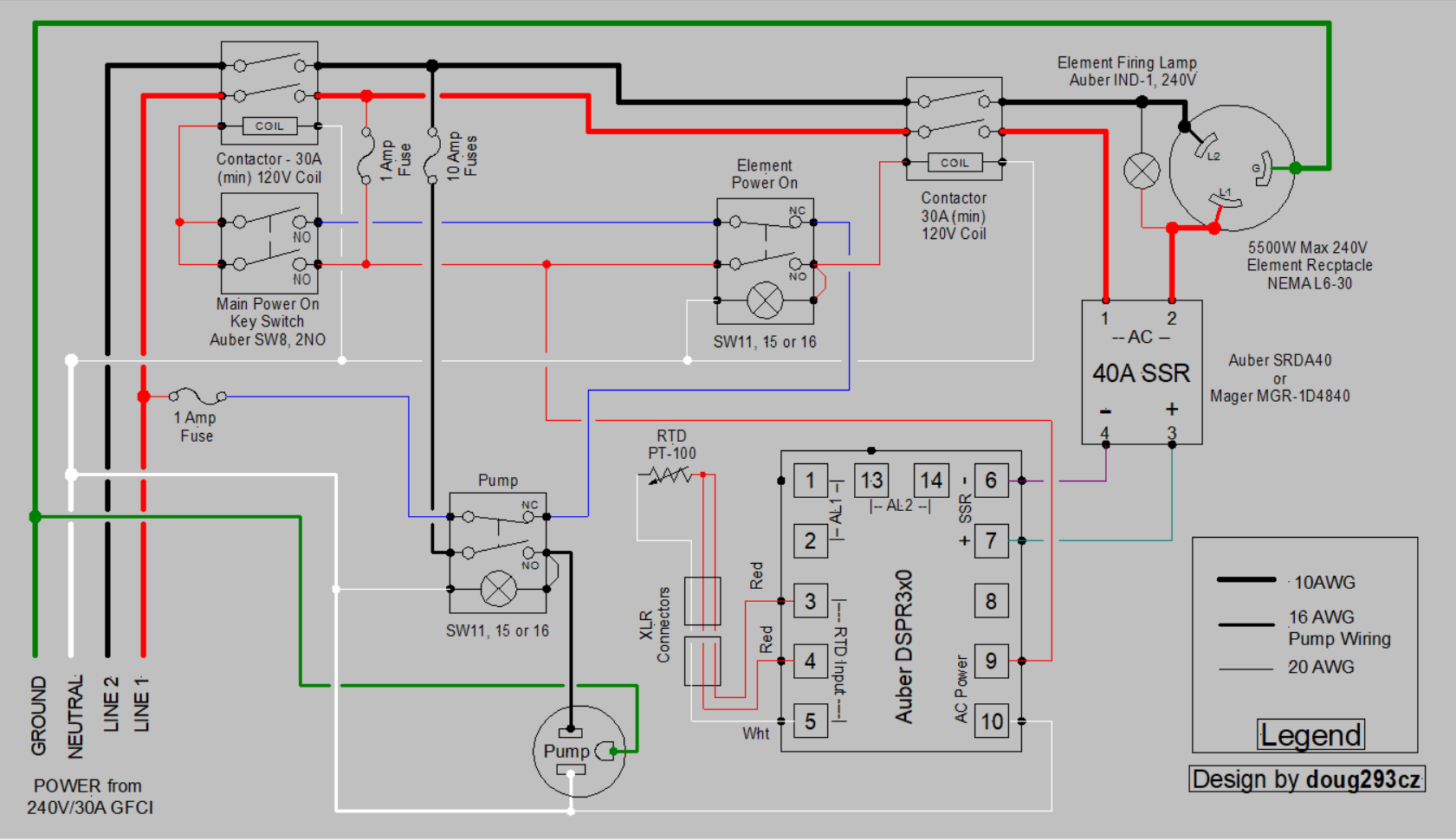
I see 10 ga used commonly for 240V 30amp circuit within a panel. But often, one of the 240 legs is split out to a switch, led or other 120v item and 14ga or 18ga is used for this portion. See circled section in wiring schematic below. Since the overall circuit is sourced from a 30 amp circuit, how is it possible to transition to a lower gauge wire safely? Note the thick line to the Main Power breaker has been identified as 10ga. A second line runs from the same terminal to an led and is shown on the schematic as 18ga. I've also seen terminal strips where 10ga runs in on one side of a bus and then smaller wires branch off. Sorry if this is a silly question, but is anyone able to explain?

Thanks,
Brian

1590672109113.png
 
Conductors size is determined in part by the amount of current flowing through it. An LED draws far less current than a heating element, so the wire gauge can be much smaller in that case.
 
Technically this wire should be protected with a breaker or fuse based in the size of the load. I have seen light sockets failed closed, especially the re-lampable types. This would be a bad situation if the light was wired directly to a 30A source. If there is a main power contractor used the light could be powered on the coil side of the contractor, which would typically be a smaller gauge. All of the coil devices could be powered with one breaker or fuse so you would not need one on each device.
 
But what about that element firing lamp? It would be much safer on the DC side of the SSR.
It doesn't perform the same function on the DC side. A DC side lamp cannot detect SSR failure, but the AC side lamp does. SSR's usually fail (or sometimes just get stuck temporarily) in the "ON" mode. If the firing lamp stays on continuoustly when the SSR should be switching or off, then the SSR has failed in the "ON" mode.

Brew on :mug:
 
I was thinking about it in terms of residential wiring. I.e 20 amp breaker... 12 ga downstream.

15amp breaker, 14ga downstream. I wouldn't run 12 ga into a box on a 20 amp and then tie in 14ga on that same circuit. But I do understand that isn't 18ga to feed the low power draw led makes sense. So some mixed ideas here.

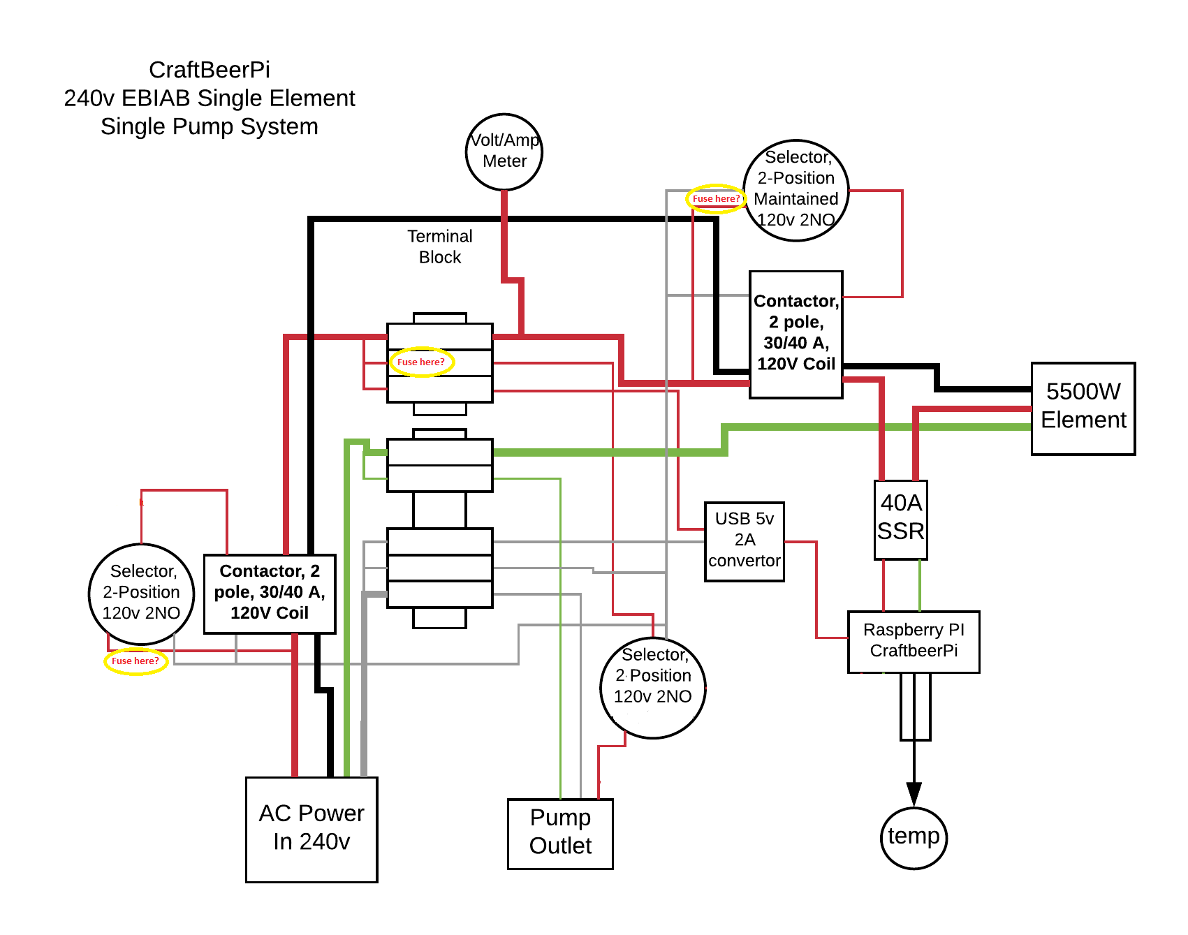
I am working from a few schematics I have collected online. I'll get something posted up shortly. I'm interested in fuse protection where appropriate. Right now, the panel design is for a single element, CraftbeerPi controller, contactors, and ssr.

Thanks again for the replies and dialog.

Brian
 
Ok... Full disclosure, I found this on a reddit thread and thought it a good starting point for what I am trying to do.

Credit to the author here:


Note - the original design has a control loop on the pump with a 3 position switch. I'm leaving that out of my system for the time being. It will be a future update.

The switches on the 120v side for the contactor coils could get fuses to protect the light per the diagram above, correct? I'm assuming I could use an inline DIN fuse holder to accomplish this? I've noted suggested fuse locations for the illuminated switches/coil and DIN rail.

1590709180471.png


Does that make sense?

Brian
 
Almost. You don't need the fuse at the element enable switch. Just pick up the 120V from the fused terminal block.

The original design has some issues:
  • Neutral is shown running to each of the switches. There is actually no place for the neutral to connect on those switches. Lighted switches need neutral (if they have 120V lamps), but they also require some additional wiring not shown on the diagram.
  • There is no way to tell if the SSR is actually following the commands of the controller, or if the SSR has failed.
Brew on :mug:
 
I would do it like this. You can fuse all of your smaller wires at one point where it steps down from the 10 gauge wire. The volt meter would also need a fuse for the other hot leg.
1590709180471.png
e
 
Two schools of thought here... its impractical to protect every sub-current device like an LED in parallel with the element. But there are rules and compliance requires following them. My feeling is, in the example of an LED (and its supporting circuitry)... it couldn't draw 30A at the LED/circuit anyway if shorted there, so would burn open, acting like a fuse. Therfore protecting it with a fuse is (by physics, not by rules) unnecessary. Now on the other hand, if you had a switch which fed a relay coil, and that coil shorted, that circuit could likely carry more current than the wires support, so they get hot and glowy. In this case, its probably prudent to circuit protect that.
 
if we're talking national electrical code, there are provisions which allow for conductors to be protected by upstream overcurrent protective devices with ratings greater than the maximum permissible ampacity of the conductor. they are formally defined as 'tap conductors' and have various restrictions based on length of the tap, ratio of tap conductor ampacity to upstream protective device, etc. the same nec rules would not directly apply to internal wiring of a brew control panel. closest applicable standard would be ul 508a which governs listed industrial control panels and has similar tap provisions for internal panel wiring. some of the fancier pre-assembled brew panels out there are available with a ul listing, this is the standard those panels are built/tested to.

all that being said, nothing wrong with adding additional fuses for additional protection. remember, codes define the minimum requirements, no problem going above and beyond.
 
This is always a pretty grey, highly debated area of discussion. First, this is a home built control box that it only tethered to your NEC-compliant, inspected home wiring but the box won't ever be inspected. Neither the box, nor the entire assembly out to the element, are being UL certified. What you're trying to do is make the box as safe as can be reasonably accomplished. For me personally, I try to use the smallest wire gauges as practical for small accessory connections. If you use 22 gauge wire to feed a PID's power circuit, it's plenty for its intended usage but the wire will burn open like a fuse if something inside the PID causes a dead short or significant over-current. You're not really going to protect the PID from damage with a fuse in the supply circuit because if it pulls more current, something was already going sideways in the internal electronics. I've never heard of the SSR control circuit causing any problems upstream either.

Taking a full 180 though.... A 10 pack of low current fuse holders is what, $6? You can even go nuts and put in DIN rail mounted 1 amp circuit breakers for less than $10 each.

no doubt nec doesn't apply inside the panel, i was just pointing out that the the nec (and the more applicable ul 508a) specifically allow for 'undersized' conductors if they meet a certain criteria. this does seem to fly in the face of the commonly accepted 'never size a wire smaller than the fuse/breaker protecting it' philosophy but it is allowed and allowed in a safe manner. but like you say, these small fuses/breakers are cheap, no problem putting one in, i did in my panel build.
 
For the 120v coming off one leg of the 240 coming in, couldn't you fuse it right up front, then run the hot to a bus that serves all the 120v consumers in the box? As long as the fuse is sized to handle the current and matches the wire size for your 120v circuit, shouldn't that suffice?
 
For the 120v coming off one leg of the 240 coming in, couldn't you fuse it right up front, then run the hot to a bus that serves all the 120v consumers in the box? As long as the fuse is sized to handle the current and matches the wire size for your 120v circuit, shouldn't that suffice?
Yes. That is pretty standard design practice.

Brew on :mug:
 
... If you use 22 gauge wire to feed a PID's power circuit, it's plenty for its intended usage but the wire will burn open like a fuse if something inside the PID causes a dead short or significant over-current. You're not really going to protect the PID from damage with a fuse in the supply circuit because if it pulls more current, something was already going sideways in the internal electronics. I've never heard of the SSR control circuit causing any problems upstream either ...

Not to hijack the thread, but I had this happen on my last brew.

On my hybrid stovetop/RIMS setup, the input side of the PID blew out on a long boil of a RIS. I haven't desoldered the boards to find exactly what caused the problem, but it was enough to lift the traces off the PCB.

Has anyone had a similar experience?
 
How do you know that? Unless you have data from a teardown of both your unit and the corresponding Auber unit, it's just speculation.

Brew on :mug:

I'm 92% certain of it. It often isn't hard to figure out where Auber sources much of their stuff.

And, for not having the unit in my hand, and relying on memory, it was just the lacquer that lifted on one trace. It was the PS board. When I get around to it, I'll desolder the board and figure out which component failed.
Not convinced. There are old posts on HBT where people would claim that "this ???? PID is the same as the Auber SYL-xxxx", and then show pictures of circuit boards from both that are completely different. You could be correct that the PID comes from the same manufacturer that makes Auber PID's, but that doesn't mean it is the same as any of the Auber PID's (they have many models). It could be the same as an Auber, but that's not proven.

What is the brand and model number for your unit, and what is the identical Auber unit? And, who is the actual manufacturer?

Brew on :mug:
 
Back
Top