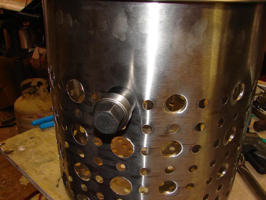
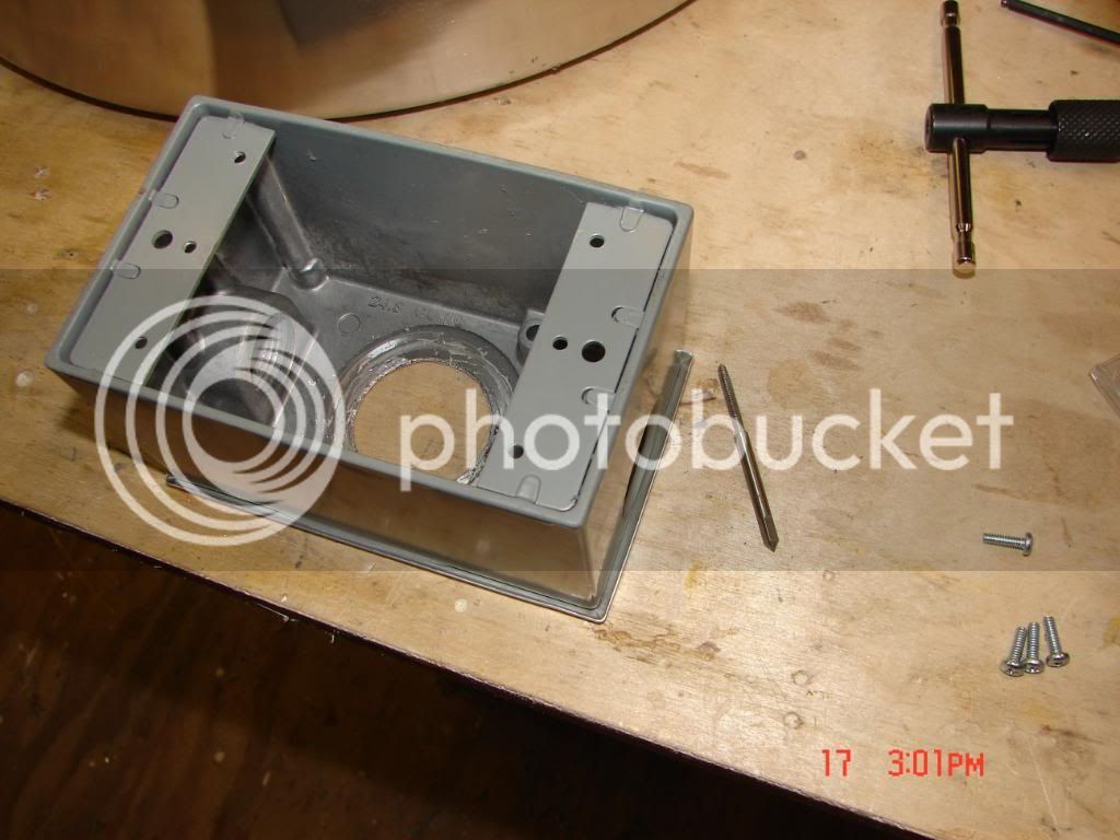
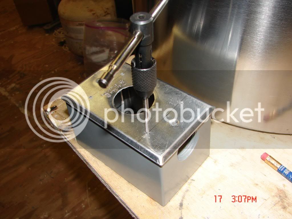
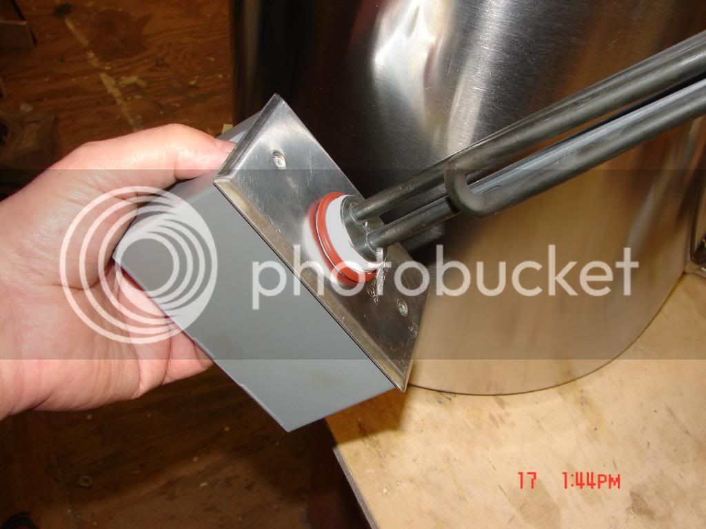
I used two different size punches for the weldless fittings and the element. I used the smallest one, 13/16", for the weldless fittings and I used the 1 1/8" for the element. I'd have to check the sizes of them again when I get home to remember the precise sizes. You can't use the same size punch for the element and 1/2" fittings. Using one size would create either holes too large for one or holes too small for the other.
The Harbor Freight punches are great for the few holes you will punch in the kettle. They are just made with inferior materials and manufacturing processes. The small punch especially won't hold up to much repeated use.
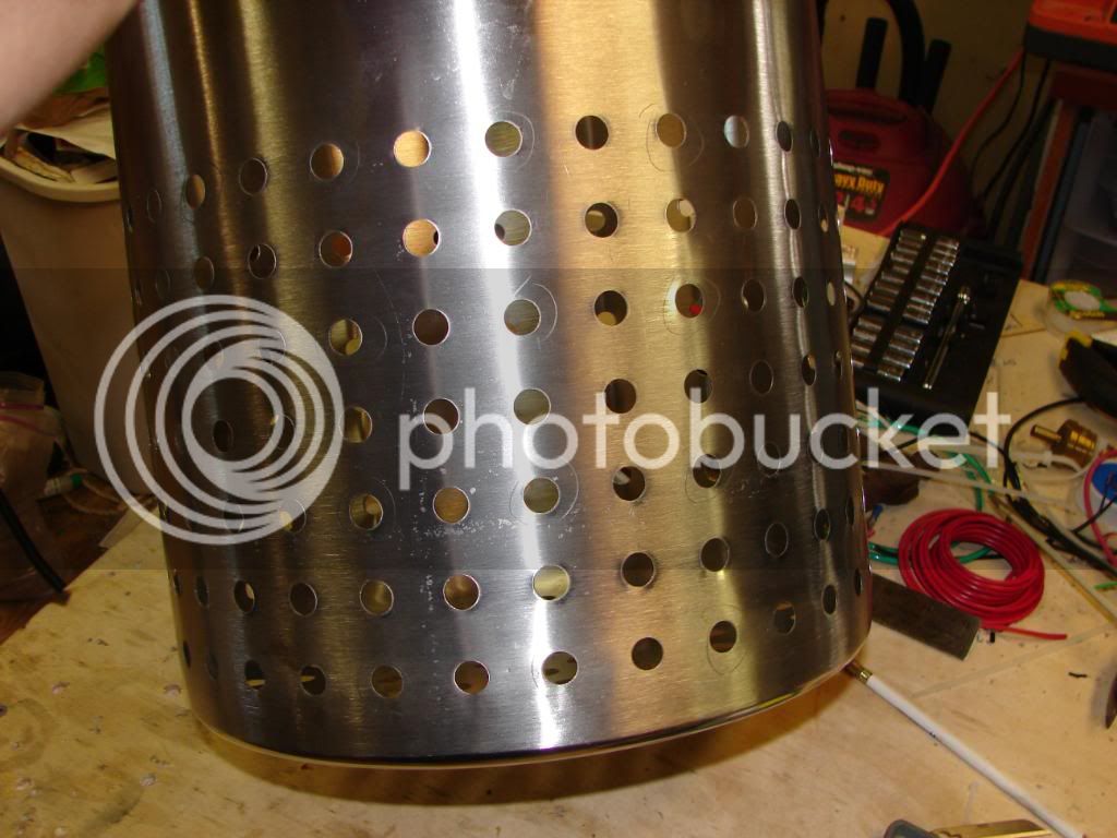
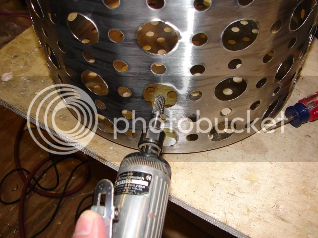
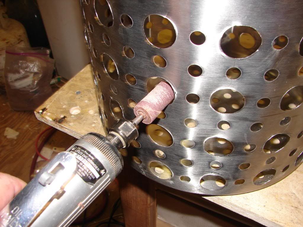
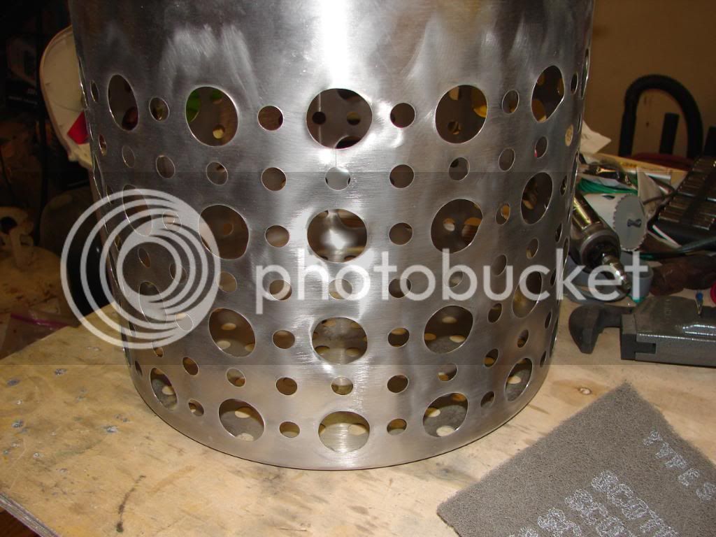
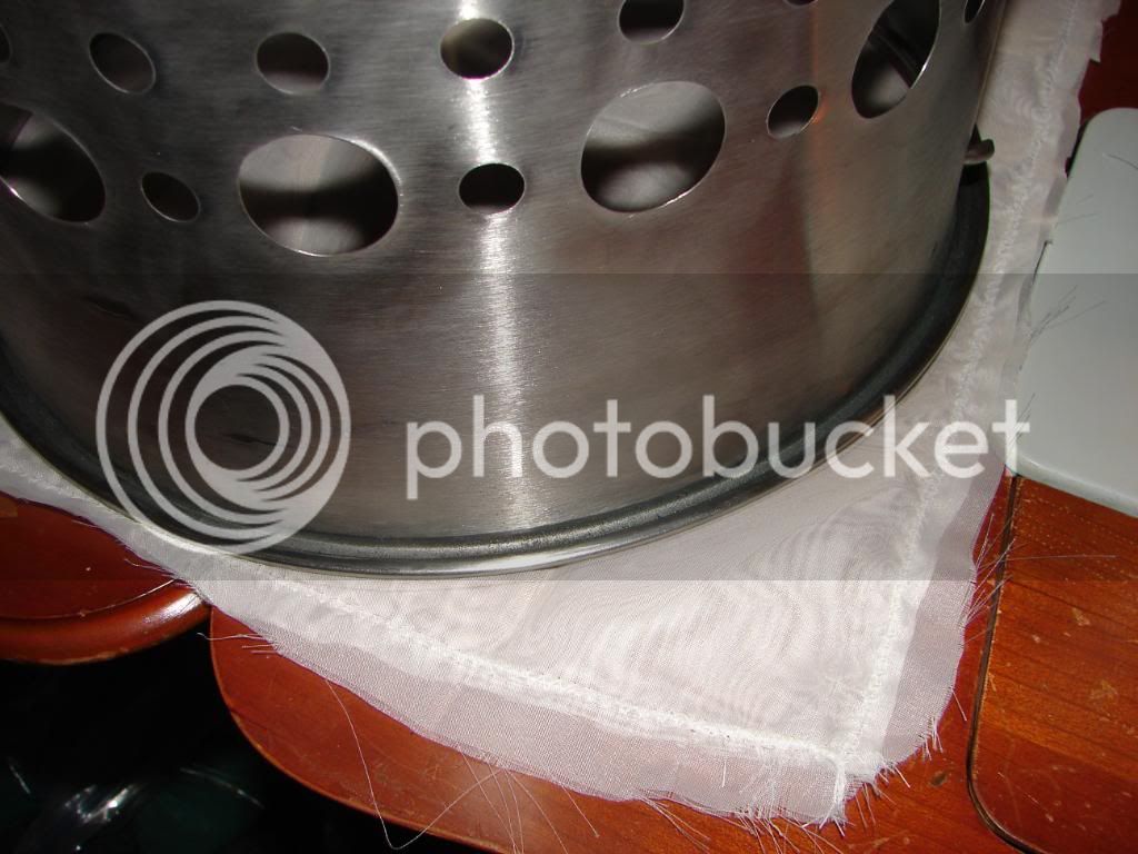
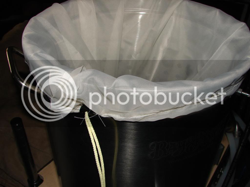
I knew the steamer basket would give the HF punches more than they could handle. The Greenlee punch laughed at the basket and asked for more. The only real draw back was the thin metal of the basket itself. Most of the holes popped through very clean but if I didn't get the punch exactly in the center of the pre-drilled hole it would leave a little tag on one side. If the basket was a bit thicker I am sure all the holes would have been perfectly clean with very little finish work needed.
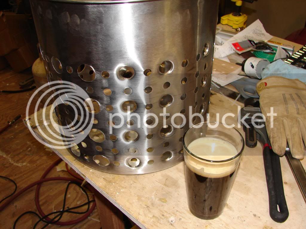
As for the bottom, there are so many holes in it and they are close together I decided to go with what I have done so far. The Greenlee punch I have is 1 1/8" and is too big to use on the bottom anyway. I may purchase a 13/16" Greenlee if I need to open some holes on the bottom. There is still room on the sides to put more holes if I don't get good enough flow.
At the time I was putting everything together$80.00-$100.00 for two punches was more than I wanted to spend but in retrospect it is what I should have done. Now that I am on the other side of the build buying the Greenlee punches one at a time doesn't give me indigestion.


 !
!