augiedoggy
Well-Known Member
ebay. I think I paid like $125 for it... it did have some goodies like wire ducting I was able to repurpose.

Got some more work done recently. I sheetrocked my basement the last week or so, so the focus has been elsewhere.
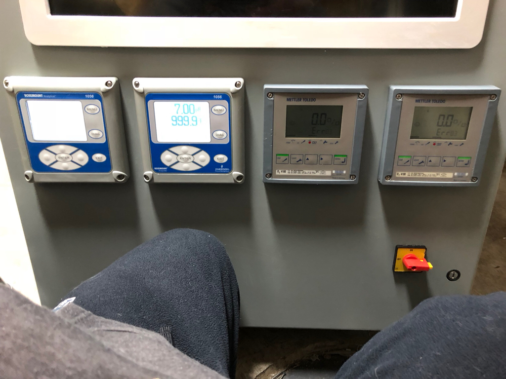
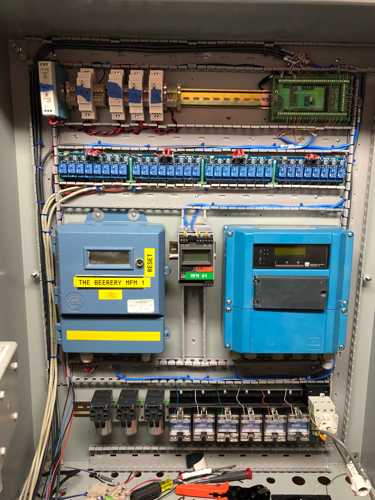
Have dual pH transmitters ( 4 total pH inputs available ) then 2 DO transmitters.
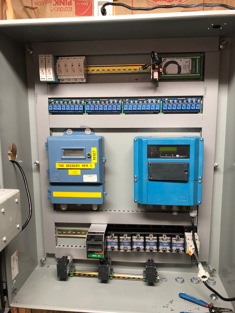
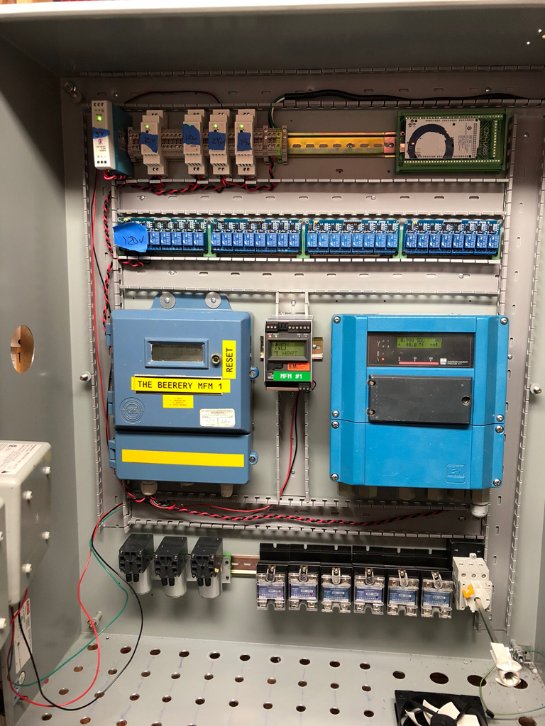
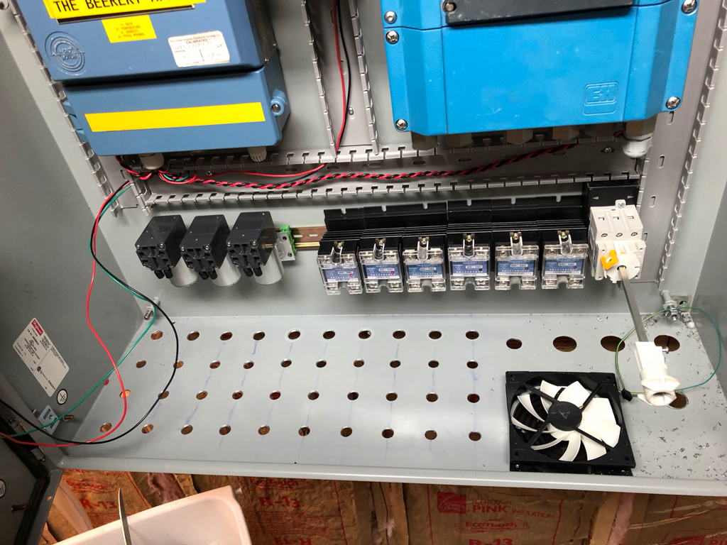
Re-organized the interior to make room for the 2 mass flow meters for real-time gravity from the mash tun and boil kettle. Then also the 3 mini vacuum pumps for the purging of the vessels.
Hopefully getting my power blocks today so I can really start wiring.
The panel has 4 120mm fans going in. 1 in the bottom ( all I have room for), 1 in the side, and 2 exhaust on top.Are you planning for any active cooling for those ssr's. I really like the look of your panel layout!

Why not put it on top with the heatsink sticking out of the panel like the electric brewery type
")
I always thought it was better to just use the bare wire when it came to larger wires like the 6 awg? The contactors I bought have connections that accommodate them..
Is that a crimping tool I see at the bottom of the 1st picture? Are you using ferrules to terminate your wires? If so, can you provide details on what tool and ferrules you are using?
I am having a hard time finding a tool that can crimp up to 6 awg wire. Most crimpers only go up to 10 awg, and I'm building a 50 amp rig so I need something that can do 6 awg. There are some that can do higher gauge wire, but they can't do smaller than 10 awg. I can't justify spending money on a tool that will only be used to crimp about 6 wires.
I found a lightly used set of KNIPEX - 97 53 09 - Self-adjusting crimping pliers on Ebay last year and they will handle everything from 5AWG - 28AWG by switching a lever on the side for larger AWG's. If you have a lot of crimps as I did they are well worth the investment.
Although ferrules are not mandatory they do solve the problem of stray strands especially from smaller gauge wires.
Is that a crimping tool I see at the bottom of the 1st picture? Are you using ferrules to terminate your wires? If so, can you provide details on what tool and ferrules you are using?
I am having a hard time finding a tool that can crimp up to 6 awg wire. Most crimpers only go up to 10 awg, and I'm building a 50 amp rig so I need something that can do 6 awg. There are some that can do higher gauge wire, but they can't do smaller than 10 awg. I can't justify spending money on a tool that will only be used to crimp about 6 wires.
My mega is not powering anything
What type of SSR do you have that uses a coil?How do you use the Mega to emulate PID control of an SSR without using power from the Mega to drive the coil on the SSR? I put an ammeter across mine, and it's drawing about 10mA.
What type of SSR do you have that uses a coil?
the Wifi shield must be making the difference then. I am using a serial connection myself. but am going with ethernet on a future build Ive started."Coil" is probably the wrong term, but I use it out of habit. The SSRs I used are 3-32VDC control. At 5v, they draw a measured 10mA. I'm also using a 12v power supply for the Mega. In comparing notes with @BrunDog, the only substantial difference between what he's running and my setup is that I'm using the WiFi shield instead of an ethernet shield.


Tell us more about the vacuum pumps. Are you going to draw vacuum on the system to rid it of O2? If so, will the vessels hold the pressure?
Hmm we use the K&N version of those pumps for ink on the UV printers I service.. On the versions we use, the diaphragms do have a tendency to rupture on the pumps if the filters start to plug and create resistance. Are you sure those will hold up?https://www.aliexpress.com/item/12V...32790027765.html?spm=a2g0s.9042311.0.0.DvU5q2
They are actually pretty powerful.
So the thought is to make all the output lines of the pumps, come to a common box. In that box I was going to mount an o2 sensor ( something like this http://wiki.seeedstudio.com/Grove-Gas_Sensor-O2/). When the pump is turned on the co2 inlet will be opened. When the sensor reads 0ppm o2, the vessesl is purged. Making all the pumps go to one box saves on the sensor costs.
I will be using these kettles I designed http://www.********************/stout-tanks-and-kettles-llc/ and they are rated for pressure.
Hmm we use the K&N version of those pumps for ink on the UV printers I service.. On the versions we use, the diaphragms do have a tendency to rupture on the pumps if the filters start to plug and create resistance. Are you sure those will hold up?
Enter your email address to join: