My Arduino Based Brewery Build

Homebrew Talk - Beer, Wine, Mead, & Cider Brewing Discussion Forum

Help Support Homebrew Talk - Beer, Wine, Mead, & Cider Brewing Discussion Forum:

This site may earn a commission from merchant affiliate links, including eBay, Amazon, and others.

estricklin

Well-Known Member
Joined
Apr 29, 2012
Messages
2,538
Reaction score
625
Location
Oklahoma City
So I have a pretty rough start on the project thus far. I'm still missing several parts and I've got a lot of work ahead but I just wanted to go ahead and start a thread in case there are others who are trying to do something similar.

The Arduino will be mounted in an old computer case, I am using the PSU that was in it to power the Arduino, and my 12 volt wort pump. I am going to use some silicone and O rings to make the case as waterproof as possible, but it shouldn't matter much anyway since it's going to be 8-10 ft away from my kettle.

This will be for a BIAB system for now, but I will be upgrading it to a full 3 vessel later. I just wanted to get away from the propane and get this up and running as soon as I could; the extra 2 kettles I will need for a 3 vessel system can wait. I have a 25 gallon Concord with a Camco 5500 watt element for now.

One of the things I love about the Arduino is how easy it is to upgrade/change things. I am doing this project because I want an electric brewery, but I'm also doing it because I love to play with electronics and build things. I've already learned so much from this project, and it's not even over!

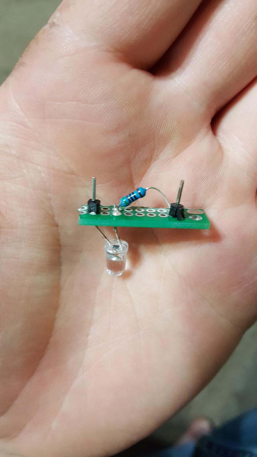
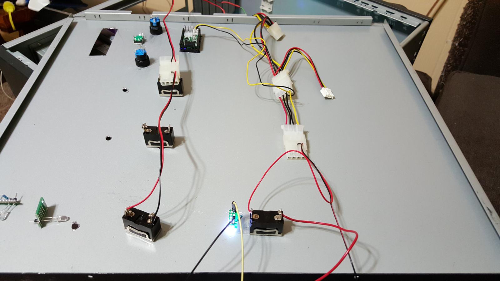
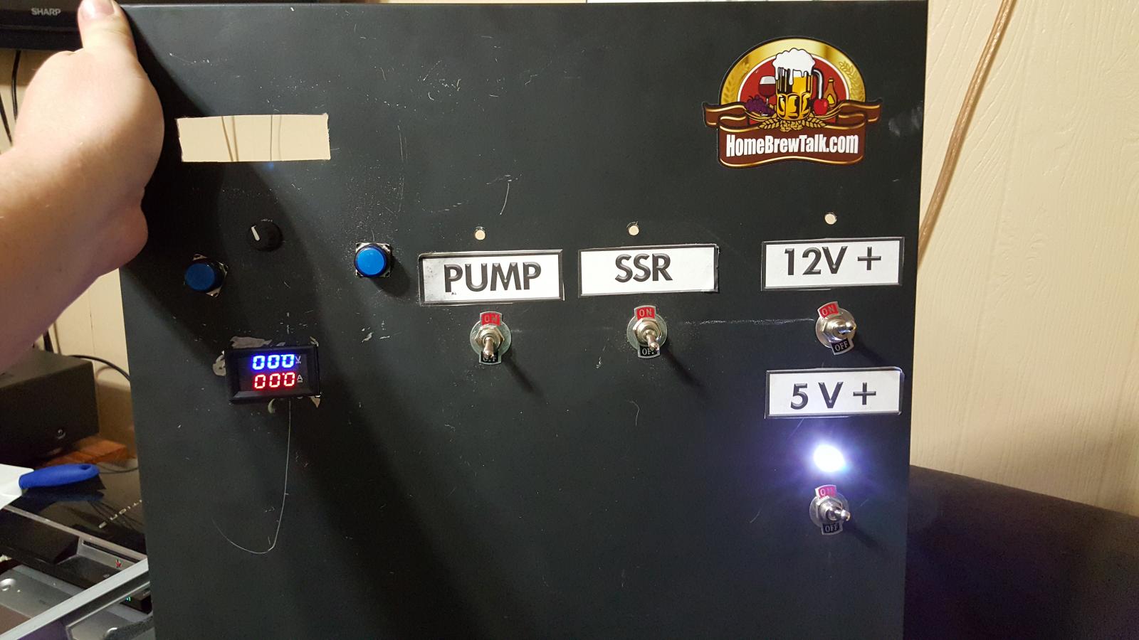
Here are a few pics, I will keep everyone updated as I go.

This is just some pics I snapped while I was doing some testing.

I will be taking some videos as well.
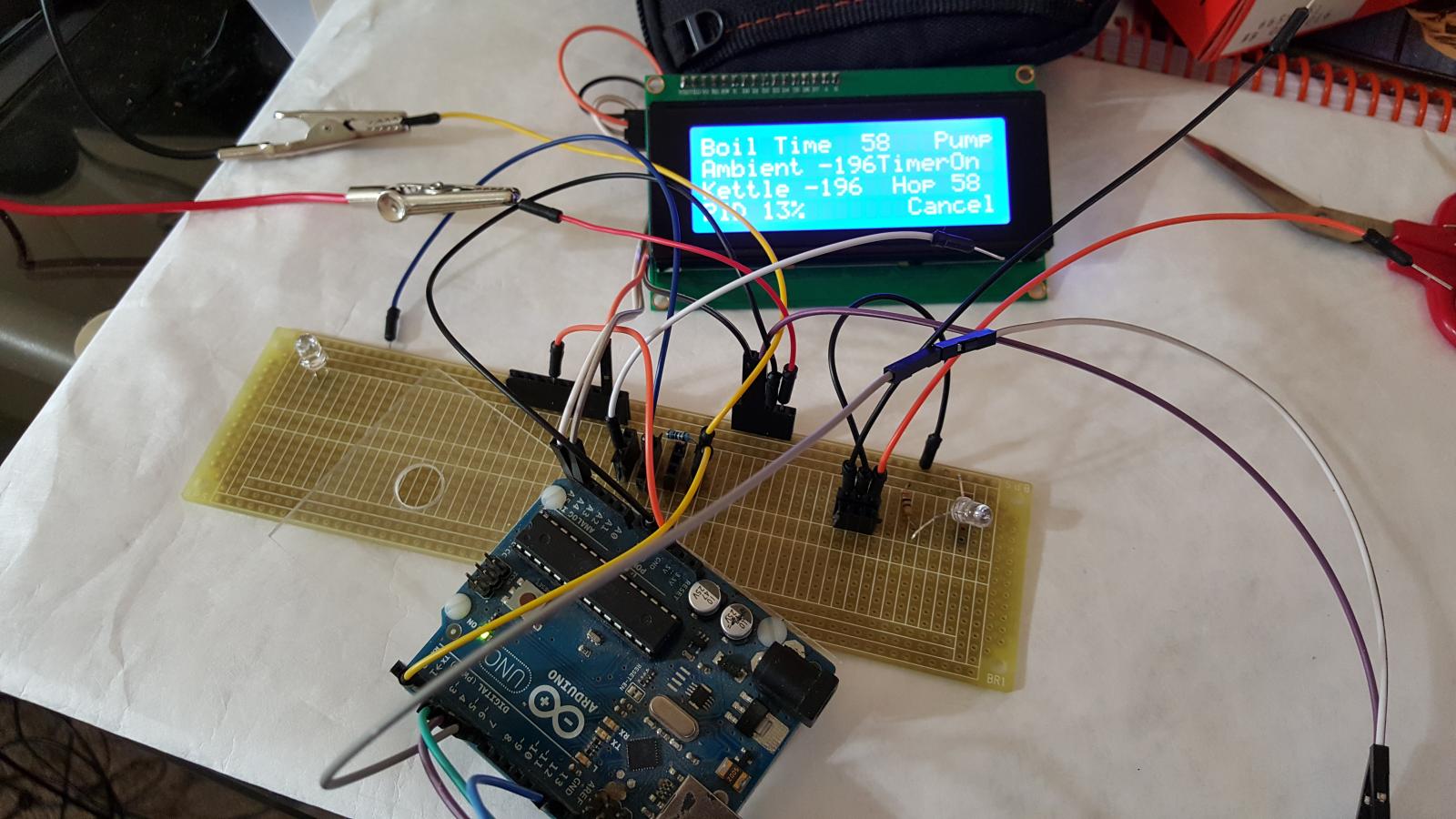
20160213_124419.jpg


20160221_190558.jpg


20160221_190611.jpg


20160221_190640.jpg
 
What are you using for temperature measurement? DS18B20?

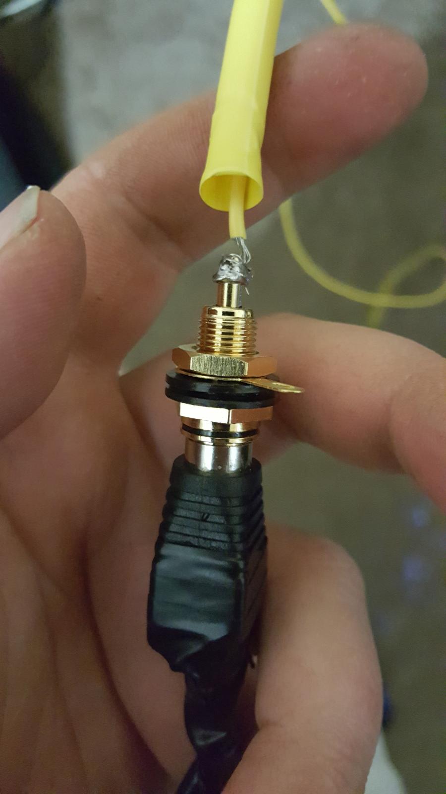
Exactly, I have 2 of them, one for ambient and the other for the Kettle. Eventually I will need more but as I'm sure your aware, it's very easy to add them since you only need one data wire for all the sensors. I am connecting them all via an RCA jack, I may in the future use an Ethernet connector. I really am not sure if I need a separate connector for all the temperature sensors.
 
I may create a Boil control 'duino some time, so I was curious.

How are you getting the sensor into the kettle? Thermowell? I've got a bunch of DS18B20's with short stainless sleeves, I wonder if they will work without the thermowell
 
I think what I plan to do is insert the probe through a piece of copper and just put a short 90 on it at the bottom, kind of let it be a couple inches above the element. Then I would drill a small hole at the top of the kettle to insert the tubing through. The worst problem I've come across is the temps sensors are only 1 meter long, so I will have to add some wire but 1 meter should get me out of the kettle pretty easy.

My code is pretty long, but I will post it on here for all to see soon. I basically have a menu that is controlled with 2 push buttons and a rotary encoder. It's something like this after the splash screen:

Settings <> Preheat <> Strike <> Boil
Settings >> empty for now, will have a number of things in here later.
Preheat = Sets up the PID and keeps the water at 145F. This is for me to use the night before if I want to shorten my brew day a bit.
Strike >> Enter Strike Temp >> Strike mode just heats the water up to a desired point, then sounds an alarm until a push button is pressed.
Boil >> Enter Desired Boil Time >> Hop Timer >> Enter a hop timer >> Boil Mode, has a manual PWM controlled by the rotary encoder.
Sounds an alarm when the hop/boil time is up.

There is always a cancel button that can be used to get back to the main menu, the pump is controlled manually through a relay, but the Arduino can "see" whether the pump is on or off, and displays it's status.
 
Here is just the code form my boil function. I am not a very good programmer unfortunately, I have used javascript quite a bit, and C regularly kicks me the in ass. I will add some comments later if anyone is interested.

Code:
void boil() {
lcd.clear(); 
delay(200);

 
getBoilTime();
lcd.clear(); 
delay(250);
getHopTime();
lcd.clear(); 
delay(250);
  boolean playBoilAlarm = true;
  boolean playHopAlarm = true;
  int oldPos;
  int newPos;
  int boilPower = 80;
  int boilPowerOutput = 0;
  unsigned long previousTime = millis();
  unsigned long boilTimeR;
  unsigned long hopTimer1R;
  boilTimeR = previousTime + boilTime;
  hopTimer1R = previousTime + hopTimer1;
 
   rightButtonState = digitalRead(4);
    while (rightButtonState == HIGH) {
      rightButtonState = digitalRead(4);
      previousTime = millis();  
      unsigned long boilTimeRemaining = boilTimeR - previousTime;
      unsigned long hopTimeRemaining = hopTimer1R - previousTime;
      if (boilTimeRemaining >= previousTime) {
        if (playBoilAlarm == true) {
          analogWrite(buzzer, 140);
        }
        else {
          boilTimeRemaining = 0;
          analogWrite(buzzer, 0);
        }
      }
      if (hopTimeRemaining >= previousTime) {
        if (playHopAlarm == true) {
          analogWrite(buzzer, 140);
        }
        else {
          hopTimeRemaining = 0;
          analogWrite(buzzer, 0);
      }
      }
     oldPos = myEnc.read();

        sensors.requestTemperatures();
        
        ambientTemp = sensors.getTempFByIndex(1);
        kettleTemp = sensors.getTempFByIndex(0);
        lcd.setCursor(0,0);
        lcd.print("Boil");
        lcd.print(" ");
        lcd.print(boilTimeRemaining/60000);
        lcd.print(" ");
        lcd.print("Min");
        lcd.print(" ");
        lcd.print("Hop1");
        lcd.print(" ");
        lcd.print(hopTimeRemaining/60000);
        lcd.setCursor(0,1);
        lcd.print("Ambient");
        lcd.print(" ");
        lcd. print(ambientTemp);
        lcd.setCursor(0,2);
        lcd.print("Kettle");
        lcd.print(" ");
        lcd.print(kettleTemp);
              lcd.setCursor(0,3);
              lcd.print("PID");
              lcd.print(" ");
              lcd.print(boilPower);
              lcd.print("%");
              lcd.print("       ");
              lcd.print("Cancel");
              enterButtonState = digitalRead(7);
              if (hopTimeRemaining <= 0) {
                if (enterButtonState == LOW) {
                  analogWrite(buzzer, 0);
                  playHopAlarm = false;
                }
              }
              if (boilTime <= 0) {
              if (enterButtonState == LOW) {
                analogWrite(buzzer, 0);
                playBoilAlarm = false;
                }
              }
oldPos = myEnc.read();
delay(5);          
newPos = myEnc.read();
if (newPos != oldPos) {
  if (newPos > oldPos) {
    boilPower= boilPower + 5;
  }
  if (newPos < oldPos) {
    boilPower = boilPower - 5;
  }
  }
  if (boilPower >= 100) {
    boilPower = 100;
  }
  if (boilPower < 0) {
    boilPower = 0;
  }
boilPowerOutput = map(boilPower, 0, 100, 0, 255);
analogWrite(11, boilPowerOutput);
    }
       mainMenuDisplay();

}
 
Worked on the temp sensors last night a bit, soldered them up and used some heat shrink around the connections, and wrapped the added wire with electrical tape from start to end.

20160228_201425.jpg


20160228_201631.jpg


20160228_204323.jpg
 
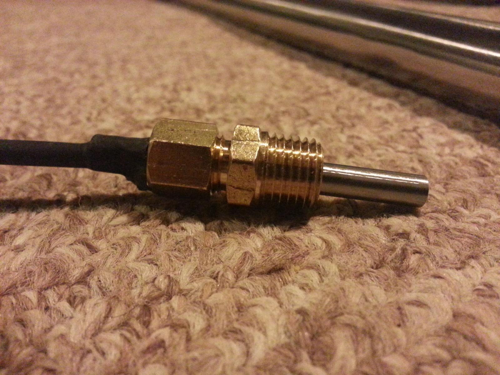
For reliability I'd stay away from parasitic mode on the DS18B20s. As for thermowells, you can easily make them with pieces/parts from lowes/depot/etc as follows:

IMG_20131022_074113.resized.jpg

This is a length of 1/4" copper refrigeration tubing, a brass 1/2"x1/4" bushing, and a 1/4" brass nipple. Simply wire/solder up your DS18B20 (that's 23 gauge wire from cat 5 cable), deposit a bit of thermo paste in the bottom of the thermowell (I use a slender disposable dropper) and shove the DS in. You can close up the bottom of the thermowell with a few solid bits of solder and just hit it with a MAPP torch while holding vertical on a surface that wont grab on to the solder. On this one I was compelled to file it to a round end. Nice part is it's really inexpensive and you can make the thermowell literally any length you want.
 
For reliability I'd stay away from parasitic mode on the DS18B20s. As for thermowells, you can easily make them with pieces/parts from lowes/depot/etc as follows:

View attachment 340872

This is a length of 1/4" copper refrigeration tubing, a brass 1/2"x1/4" bushing, and a 1/4" brass nipple. Simply wire/solder up your DS18B20 (that's 23 gauge wire from cat 5 cable), deposit a bit of thermo paste in the bottom of the thermowell (I use a slender disposable dropper) and shove the DS in. You can close up the bottom of the thermowell with a few solid bits of solder and just hit it with a MAPP torch while holding vertical on a surface that wont grab on to the solder. On this one I was compelled to file it to a round end. Nice part is it's really inexpensive and you can make the thermowell literally any length you want.

Nice! Thanks for that. I will make a note of using them in parasitic mode, but since I have them soldered that way already I will try to use them like that, haven't had any problems in testing so far. If I run into problems I'll know where to look though.
 
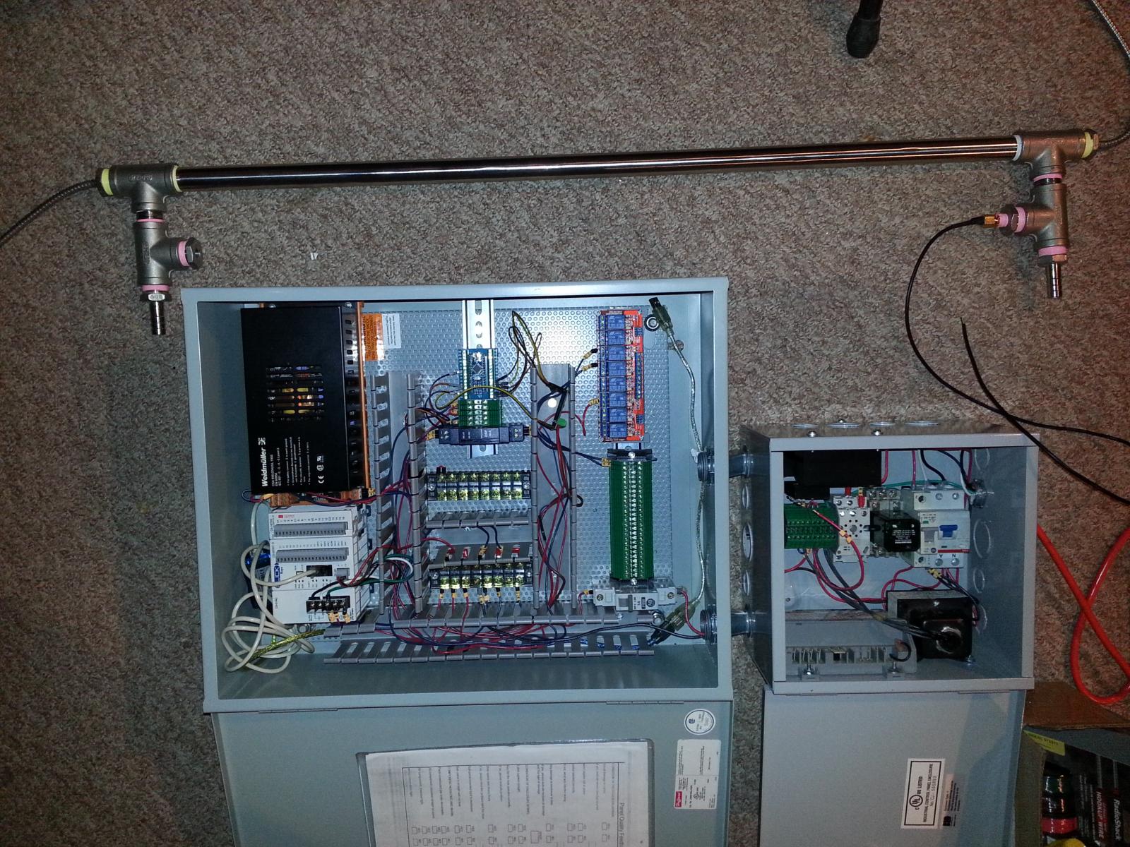
For temp measurements in pipes I just used a compression fitting with the standard ebay "waterproof sensors" and threaded into my rims setup. I've only tested with water but it worked well. I'm using an arduino nano as a cheap I/O expansion module for my plc via modbus. Setup works well but still have a lot left to build left before I'm brewing.

tmp_10346-20150323_233700-1340521686.jpg


tmp_10346-20150325_231245-1870640302.jpg
 
For temp measurements in pipes I just used a compression fitting with the standard ebay "waterproof sensors" and threaded into my rims setup. I've only tested with water but it worked well. I'm using an arduino nano as a cheap I/O expansion module for my plc via modbus. Setup works well but still have a lot left to build left before I'm brewing.

What all do you have going on there? That's a lot of relays. I am in the process of wiring everything up and there are freaking wires everywhere, I've got some looms and terminals blocks, trying to keep things as neat as possible but it's just a nightmare. So many switches and LEDs. Any advice?
 
Im using the cheap relays to isolate the contacts on my plc from the solenoid valves. As for advice..

Lay out your panel in cad/excel/back of napkin before starting. I have an interconnect speadsheet that shows where every wire is laneded. This took a long time but was worth it, especially when i havent worked on my panel in a few months.

Get some wire number labels and match those labels to your interconnect. I also use specific wire colors for hot, ground, and data.

Figure out what size panel you need from your drawing, now double those dimensions.

Find a place your wife doesnt like to go where you can build said panel.

Thanks for the advice.

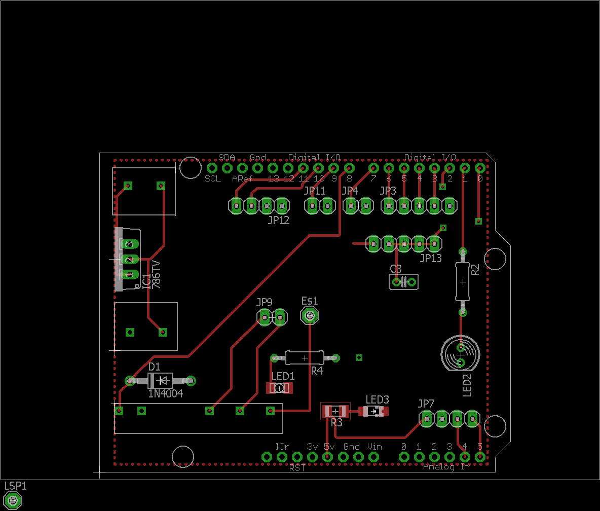
Sorry to all I haven't replied in a while, but my project train wrecked and I have a newborn in the house. I have the board laid out, to what I think is my complete satisfaction, but I will wait until i finish re-writing the sketch to have the board made, in case I make changes.

Having the board made should reduce the number of connection, and make a lot of the connections I do have much easier. I have selected a family of connectors form Molex, that I will use for this project for most of the connectors. Also for my big jumble of wires I've decided to make myself a cad diagram to follow. I'm going to use Ethernet cables for a lot of the wiring because a lot of these wires don't need to be very big. I plan to make a color chart, and for wire labeling I will most likely use little pieces of heat shrink on the ends.

For my case I am building one from 1/4 inch plexi glass.

I ditched the rotary encoder from my project, I was going to have to use interrupts to get it to work correctly, and the sketch kept getting larger, so I'm going with an "up", "down", "left" and "right" push button set now.

I'm a little upset at myself it's been over a year and I still don't have this project finished, but I have learned a ton along the way.

Look forward to posting some pics of the case, and circuit board soon.

brewShArdu.png
 
I am using an arduino mega. If you want to give the rotary encoder another try, here is my code. I am using 5 milliseconds for debouncing. It isn't perfect but it is pretty responsive/accurate in my system.

Code:
//Pins for rotation of encoder
  byte pin_EncoderA = 2;  //Green-White https://www.arduino.cc/en/Reference/AttachInterrupt
  byte pin_EncoderB = 14; //Blue-White
//Pin for button
  byte pin_Button = 3;   //Green-White-Black

//======================================================================================================================================================
//Variables, Constants, and Definitions
//======================================================================================================================================================  
//Debouncing variables for rotary encoder
  unsigned long Time_prevDebounce = 0;  //Stores the time which the encoder was last rotated
  int Duration_Debounce = 5;          //millis - Minimum length of time allowed between rotations
  
//Machine State for Rotary Encoder. Needed for Interrupts.
  byte State_PinA = 0;
  byte State_PinB = 0;

//********************************************************************************************************************
//********************************************************************************************************************
void Rotary_setup() { 
//Set the pins as inputs for the encoder and the button
  pinMode(pin_EncoderA,INPUT);
  pinMode(pin_EncoderB,INPUT);
  pinMode(pin_Button,INPUT);
//Initiates external interrupt   
  attachInterrupt(0, RotaryPinCheck, CHANGE);
} 
//********************************************************************************************************************
//********************************************************************************************************************
//External interrupt routine
void RotaryPinCheck(){
//Reads state of both decoder pins
  State_PinA = digitalRead(pin_EncoderA);
  State_PinB = digitalRead(pin_EncoderB);
}
//********************************************************************************************************************
//********************************************************************************************************************
void Rotary_loop() { 
//Determine if encoder has been rotated
   if(State_PinA == 1 && Time_prevDebounce <= millis()){
     if(State_PinB == 0){
       Time_prevDebounce = millis() + Duration_Debounce;
       State_EncoderCW = 1;
     } 
     else{
       Time_prevDebounce = millis() + Duration_Debounce;
       State_EncoderCCW = 1;
    }
  }
} 
//********************************************************************************************************************
//********************************************************************************************************************
 
I am not using any form of hardware debouncing. Only the interrupt.

I might have to use your code for encoders. I could never get them to work with my code, but I was also using interrupts for the PID so I'm not sure if that created some sort of conflict.
 
Back
Top