Motorized Monster Mill Build

Homebrew Talk - Beer, Wine, Mead, & Cider Brewing Discussion Forum

Help Support Homebrew Talk - Beer, Wine, Mead, & Cider Brewing Discussion Forum:

This site may earn a commission from merchant affiliate links, including eBay, Amazon, and others.
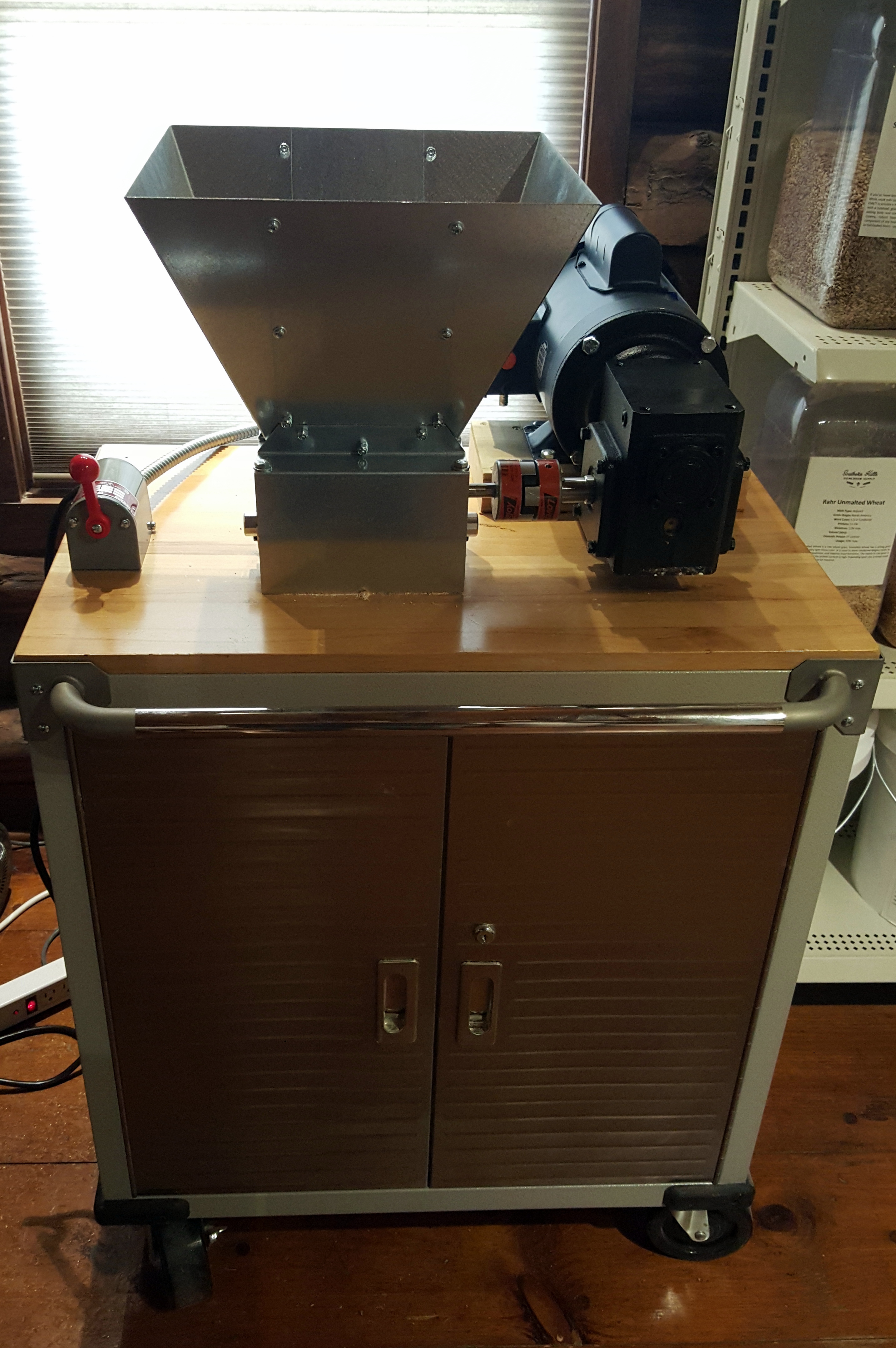
Motor will work but expensive. Check ebay should find something around $130. My reducer doesn't have a base and I haven't had any issues. When you attach it to the motor and mill its not going anywhere.

Nothing in the $130 ball park has a base and face mount as well as being Cap start and 56C.

Understood about the base. Cheers!
 
You're right I didn't realize the price has went up in the last year. You're on the right track.
 
About to finish sourcing my similar build and struggled to find a well priced 1HP Motor with these specs: 56C, Cap Start, Base and Face Mounting - Alas I found this:


http://www.surpluscenter.com/Electr...115-230-VAC-56C-TEFC-LEESON-MOTOR-10-2700.axd


Also, this BASE for the 10:1 Speed reducer looks like it might make mounting it a bit easier. Thoughts?


https://www.surpluscenter.com/Power...SE-FOR-175-FRAME-GEAR-REDUCER-13-175-BASE.axd


The base will help spread the load of the motor if you're going to hang it off the gear reducer. However, you'll still need another spacer under that one (~3/4" thick) to raise the shaft of the gear reducer to line up with the shaft on the mill.
 
The base will help spread the load of the motor if you're going to hang it off the gear reducer. However, you'll still need another spacer under that one (~3/4" thick) to raise the shaft of the gear reducer to line up with the shaft on the mill.
 
Drunkenmonkey, that is a very nice brewery! I have pretty much the exact same stuff only a smaller 20 gallon system. Where did you get the stainless steel rollers to mount your chiller, pumps, strainer and oxy system?
 
The base will help spread the load of the motor if you're going to hang it off the gear reducer. However, you'll still need another spacer under that one (~3/4" thick) to raise the shaft of the gear reducer to line up with the shaft on the mill.

Drunkenmonk, my good man. Quick question. I have attached 2 photos. The show the height difference between 1) the Motor (leeson with base) and the speed reducer and 2) the speed reducer and mill.

Is there an EXACT hight difference that would allow me to go buy corresponding blocks to put under the motor and under the reducer?

The difference between motor and reducer seems to be maybe 1/2" and the difference between the reducer and the mill seems to be 1 1/2" - does this make sense? I would hate to have the blocks JUST be off.

IMG_4172.JPG


IMG_4169.JPG
 
Can't help with the blocks but the 10:1 reducer should list the output shaft size. I had an issue with mines as well and if i can remember correctly the reducer might come with two different key sizes for the coupler. Recheck the box i remember this was a pia but turned out to be simple.
 
Here's some photos:

Can you explain the two pieces of wood under the bottom that hold the bucket? -Did you make or buy them? If buy; what exactly are they and where can I get them?

(Obviously I'm not very handy.)

I'm currently building my cart and I LOVE this simple solution for avoiding dust.

-I was thinking about buying a gamma lid and just cutting it and screwing it to the bottom of mine and then screwing the bucket in but that's a lot more complicated, slow and a bit more expensive than your "rails" solution.


Adam
 
Hey guys, I just bought a MM3-Pro and I am trying to motorize it. I was able to find this Leeson motor: https://www.surpluscenter.com/Elect...FC-LEESON-MOTOR-W-MANUAL-OVERLOAD-10-2706.axd

and I am using the switch from the original post: http://www.mcmaster.com/nav/enter.asp?partnum=7065K21 and it's wiring is as such:
09tpyc6.jpg


However, it looks like the wiring is a bit different on the Leeson motor, or at least the wiring labels are, anyway. Could somebody give me a hand with how I should be wiring this motor and switch up? I don't want to let the smoke out of this brand new motor.

I guess this is the same setup as BTokarchic, but he seems to have dropped off the face of the earth. Any help y'all could provide would be appreciated.
 
Any markings on the wires as to which is t2, t4, t6...? Can you figure that out?
 
Here is the wiring. For forward switch should be 123 and 456. For reverse the switch should be 124 and 356. So here is how you wire the switch contacts
1- L1 & T2
2- T4
3- T5
4- T8
5- P2
6 - L1 & T3

You can't turn the switch from fwd to reverse in one motion. The motor has to wind down/ disengage before switching from one direction to the other. I use the same switch and smiling motor. Took awhile to fig out wiring but it works like a charm. I created a write up on here. Search for " motorized monster mill build mm2-2.0" and you'll find it. I didn't wire it all neat and permeant at first b/c I wanted to make sure it worked first. Good luck and let me know how it turns out.
 
Yes, the wires are marked - P1, P2, T2, T3, T4, T5, T8. What's throwing me is the P2 wire.

Would I use the original switch diagram that drunkenmonk posted:
attachment.php


and just use P1 as T1 and tape off P2?
 
Here is the wiring. For forward switch should be 123 and 456. For reverse the switch should be 124 and 356. So here is how you wire the switch contacts
1- L1 & T2
2- T4
3- T5
4- T8
5- P2
6 - L1 & T3

You can't turn the switch from fwd to reverse in one motion. The motor has to wind down/ disengage before switching from one direction to the other. I use the same switch and smiling motor. Took awhile to fig out wiring but it works like a charm. I created a write up on here. Search for " motorized monster mill build mm2-2.0" and you'll find it. I didn't wire it all neat and permeant at first b/c I wanted to make sure it worked first. Good luck and let me know how it turns out.

I will definitely look up your build. One thing in your wiring is that I don't see L2, or neutral.

**Edit:** I looked up your build, I like it a lot. It's very clean looking. One thing though, we are using different motors, and that's what's throwing me. My motor is at work, but I found this image on another site that shows it's wiring:
108766d1401866445-leeson-110-motor-hookup-reversing-switch-dsc_0898.jpg
 
Accident

1- L2 & T2


In your wiring for the motor it shows T1 splitting into P1 and P2. In the wring below on the same diagram it lists P2 connected to T3 and T5. So I substituted my T1 for your P2 and the wiring should be the same. I don't think you have to worry about P2. I've seen that wiring diagram you posted and it didn't work for me. I didn't get the wiring right the first time I hooked it all up. Took a few tries and the end result is what I posted.
 
One more thing.. My motor wiring didn't have a P1 or P2. Instead it had T1 and the other 5 wires. Only 6 wires total and cap start motor as well. Should work how I told you.
 
Finally got everything wired today and milled some grain. This thing is a beast.

So, for posterity's sake, here is my finished working drum switch wiring for the Leeson M6C17FK80E 1HP motor:
R3QaaCN.jpg


SW1: T2, T4
SW2: L2
SW3: T8
SW4: T5
SW5: P1, T3
SW6: L1

Ground to switch chassis and armored cable for ground from switch to motor.

I used P1 and taped off P2. This wiring allowed me to do everything with only one connection to each switch point.

And obligatory mill picture:
75Ae3uX.jpg
 
Love this thread and I intend to do.some upgrades to my motorized mill.

Has anyone thought about mounting the mill and motor under the table? Increases work surface and much cleaner, although the entire setup may have to be taller. Good work everyone!
 
Looks like the wiring for my lesson is different. I tried wiring it like the op but it would turn my gear reducer. I'm using the same McMaster switch with the forward and reverse. My wiring is all T's

Can anyone help me out with a drawing like op's. I'm bad when it comes to this stuff

image.jpg
 
Hey my wiring looks just like yours and I wrote a post on it. Search for " motorized monster mill build mm2-2.0" and you'll find it.
 
Found it. I'll give it a shot. Quick question the nuts that come pre screwed on to the brass post. Do you remove those before wiring everything or just go on top of them and then with the other brass washers and nuts from the bag supplied.

Hey my wiring looks just like yours and I wrote a post on it. Search for " motorized monster mill build mm2-2.0" and you'll find it.
 
Yeah i think you just go on top. So its a stack.. nut at bottom, then ring terminal, then washer, then nut on top. Think that's what i did.
 
Ok so I tried it and I'm have trouble with the gear reducer spinning. When the motor is not connected to the reducer it works and spins fine. When I couple to the reducer the motor sounds like it's stalling and it doesn't turn the reducer. When I check the reducer the coupler the hooks to the motor spins easily but where it couples to the mill is very difficult to turn with my hands. I even installed the vent bolt and got nothing. Anyone have any ideas what may possibly be wrong? I called surplus center where I got the motor and gear reducer and they believed it to be the wiring. I don't know what's going on
 
Ok...with just the motor wired up does forward and reverse function correctly? If so sounds like the reducer bc the wiring functions as it should. Let me know the results and shoot me a pm if you want.
 
So I just received my newly exchanged gear reducer and I still can't get it to spin. The motor spins when not connected to the reducer. Hopefully some of you can help me trouble shoot this issue.
The links below are of the items I'm using. Anyone see any issues with these? They should work with each other right?
How's the motor and switch wired? It's possible that the field is not wired correctly and the motor doesn't have enough torque to spin the reducer.

I don't use a drum switch on my mill but a quick review indicates that there are at least two different types of drum switches being used here. It is very important to not confuse the two since they will be wired differently to a motor.

One has a double "L" contact configuration, wherein the end contacts are the same for both directions and the center contact swaps for each direction. This appears to be the McMaster-Carr product or the Dayton 2x440.
Like this:


---------

The other type has contacts like this:http://www.industrial-electronics.com/image/15-16.jpg

-----------

My Recommendation:
I'll assume you are wiring for low voltage (115vac). If you determine that you have the double "L" configuration switch then wire it per thatfatbastard post #101 of this thread. Substitute T1 for his/her P1.
 
My cousin who is a high voltage electrician took a look at my wiring and said it was wired correctly but that the motor didn't seem to be functioning properly So I had my cousin take the motor to his work to test it out. He reported that there was a dead spot in the motor. He explained it to me but it's way over my head. So I sent the motor back today. I'll report back. Hopefully I'll get a new one and there won't be any problems.

Thanks for everyone's help it's much appreciated
 
Is the Reducer just hanging off of the motor as it is bolted to the face? Or do you have a block under the reducer as well and have that bolted into the base?


On my first iteration, I had the reducer hanging off the motor. On my second iteration, I did it the other way around. Either works fine. Just make sure you've got something sturdy to mount either too.
 
Thank you so much for this thread!, drunkenmonk!

I'm about to pull the trigger on this build, but I'm wondering if anyone has seen a gear reducer that can handle 3450-3600 rpm? a 15:1 reducer isn't hard to find but they all take 1750 rpm max. 3450 rpm at 15:1 will get that mill going at 230 rpm, which I certainly wouldn't mind! I've looked and looked at all the sources listed here and a few more. Not finding anything so I figured I'd ask before "settling" on 180 rpm ;)

TIA!
 
Back
Top