TheMarkWhite
Well-Known Member
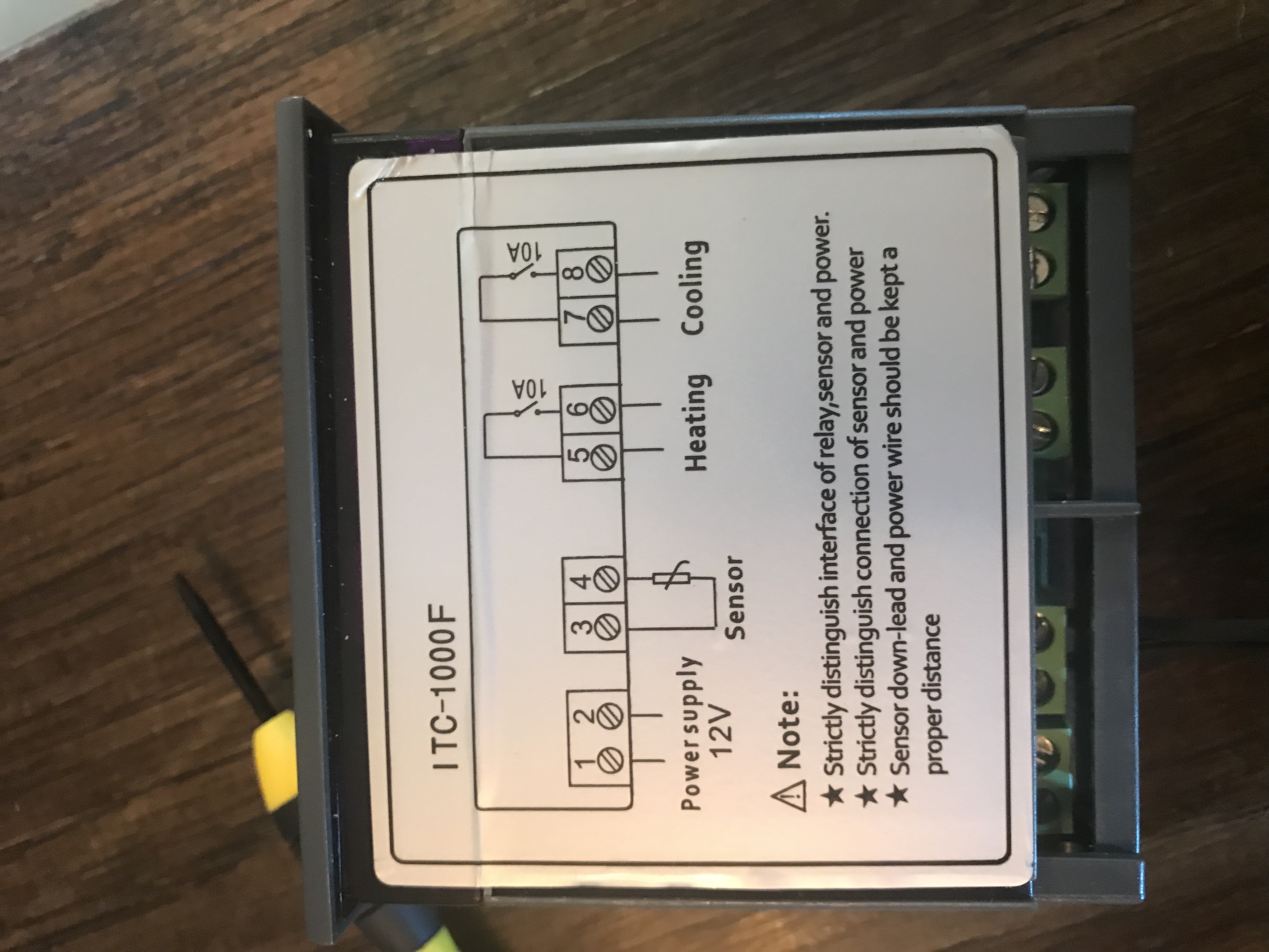
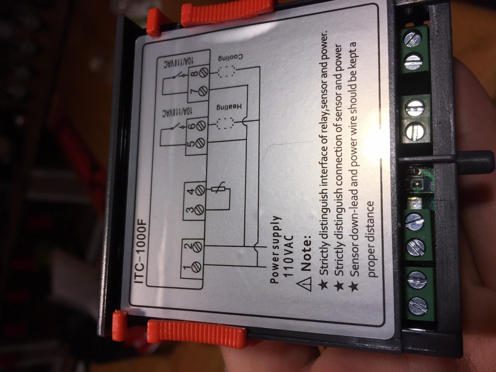
I have a Danby 4.4 freezerless fridge and want to put my STC -1000 controller in place of the stock thermostat. I found many posts with the exact same wiring diagram that’s in my fridge.
I took the black wires and ran them to terms 1 & 7. Took the red wire and ran it to term 8. Spliced the white wire from the light and ran it to term 2. nothing happens. No light and STC won’t turn on.
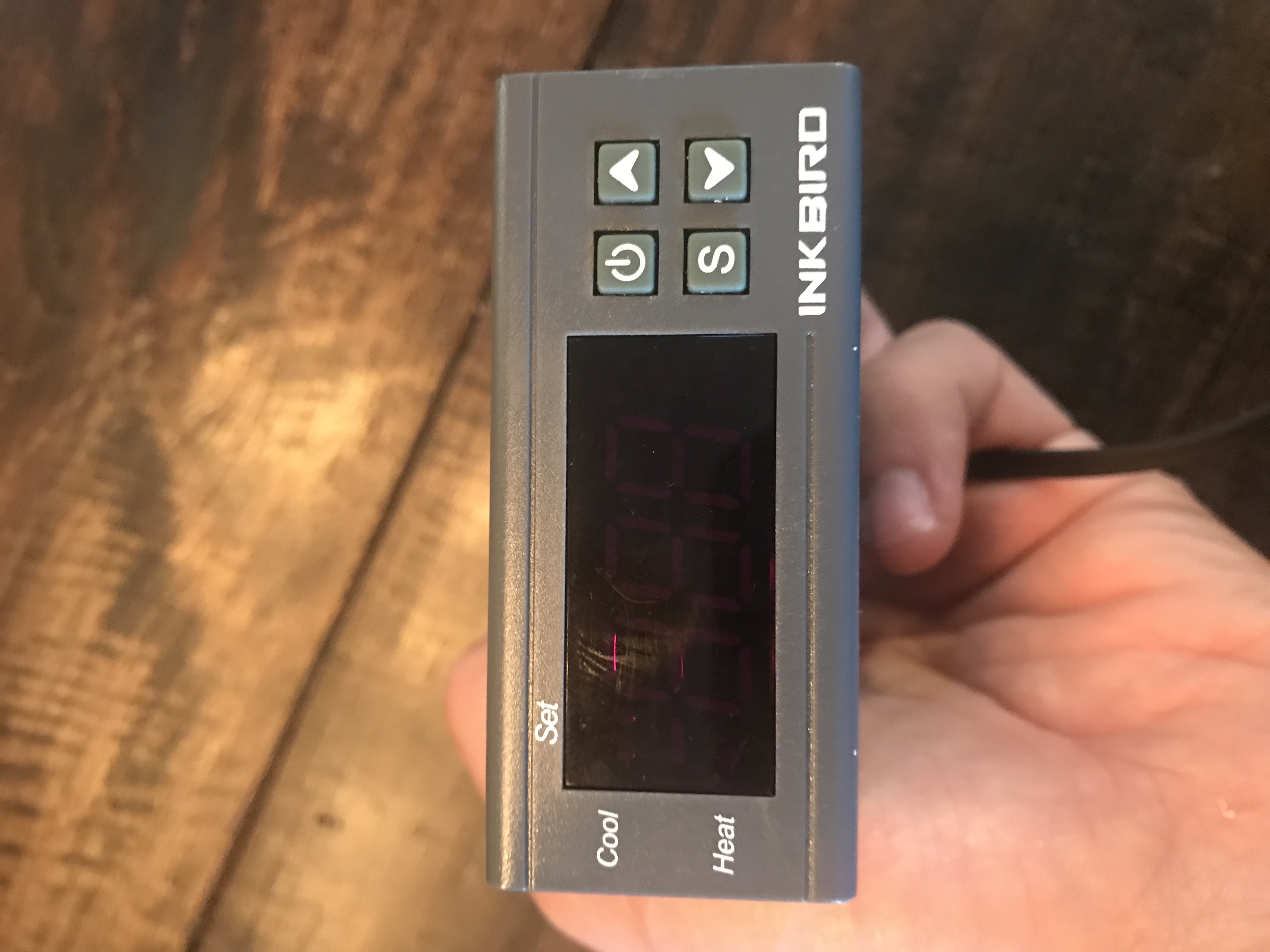
I bought the controller sometime ago and just got around to building my kegerator. Is my therm dead? Any ideas? Please help!
I took the black wires and ran them to terms 1 & 7. Took the red wire and ran it to term 8. Spliced the white wire from the light and ran it to term 2. nothing happens. No light and STC won’t turn on.
I bought the controller sometime ago and just got around to building my kegerator. Is my therm dead? Any ideas? Please help!