Indicator LED stays ON - help pls

Homebrew Talk - Beer, Wine, Mead, & Cider Brewing Discussion Forum

Help Support Homebrew Talk - Beer, Wine, Mead, & Cider Brewing Discussion Forum:

This site may earn a commission from merchant affiliate links, including eBay, Amazon, and others.

tjash

Well-Known Member
Joined
Jan 4, 2012
Messages
62
Reaction score
7
Location
Cumberland
Finally got around to testing my build last night [pics HERE, more to come] and ran into 2 problems. First, the alarm didn't work. I think I figured that out; no power supplied to terminal 13 on the PID. I corrected that, but haven't tested it yet.

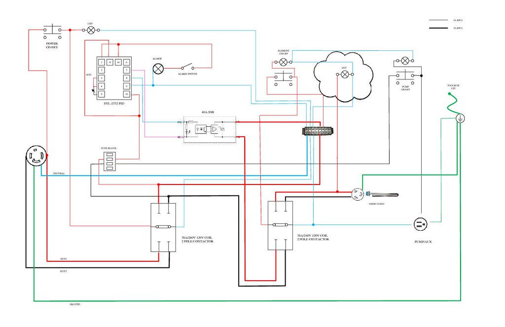
Second, I put in an indicator LED with the intent of showing when the element is receiving power. So, the illuminated switch indicates power is available, and the LED should show when power is being delivered. But, the LED is staying lit all the time, whenever the contactor for the element is closed, regardless of whether or not the PID is sending power.

THIS is the LED I'm using. And here is my wiring diagram. The LED I'm having trouble with is highlighted with a cloud.


An electrical engineer friend at work suggested that the LED is still receiving current when the SSR isn't firing via the element. Essentially, current is "backflowing" through the element from L2 (black) to N. Is that a reasonable explanation, or is it more likely leakage from the SSR via L1 (red)?

I plan to do some testing tonight, but wanted to get some thoughts from those with more experience. Otherwise, all seems to be working well and I was able to bring about 8 gallons from 50F to 150F in under 30 mins last night!
 
I can't really read the diagram (lettering is too small), but I will say this...

SSRs leak current. It's a very small amount, but it is enough to make a small indicator lamp light up. I had this same problem on my system and it confused the hell out of me at first.

If you plug something into the heater element outlet, then the leakage current will suddenly see two paths available.
(1) the high resistance light
(2) the low resistance element

Like water, electrical current will follow the path of least resistance, so the leakage current will almost all flow through the element and the light will not receive enough current to turn on.

So, with nothing plugged into the heater outlet, the light will always be on. With something plugged into the heater outlet, the light will only come on when the element is really firing and the SSR is passing through the full amount of current.

But, like I said, I can't really read the diagram so I can't comment on whether the wiring is bad or not.
 
Oh, wait... now I think I figured the diagram out.

The SSR leakage is still something to think about, but you do have the issue your EE friend was commenting on. Even when the SSR is not enabled, there is a path from the black hot line, through the element to the red hot line, through the light and then to neutral.

If you want the light to work, you have to have it truly in parallel to the heater. it has to be connected across 240V and not 120V.
 
Do you have the element plugged in? Mine does the exact same thing when I unplug the element but works perfect when it is plugged in. I believe your friends back flow is right on the mark
 
Thanks for the input. I'll see if I can post a bigger version of my wiring for anyone else interested in taking a look.

Unfortunately, it's a 120V LED. Not sure if it will function if I put 240V across it (or fry). Any way to wire a 120V indicator into the circuit that only lights up when power is delivered to the element?


I had the same issue. My light was 120V, but I needed/wanted it in parallel to the element on 240V.

I just measured the resistance of the lamp and then added an equivalent resistor in series to the lamp. Then I connected all of that across the 240V. This allowed 120v to drop across the resistor and then the other 120v to drop across the light.

Do you have a link to the actual light you are using?
 
Ah. Hadn't considered putting in a resistor. Link to the light is in the first post.
 
Those lamps have a resistor in them already to limit the current flowing through the LED. If you can see the resistor you can decode the value of it via the stripes on it.

I've always sucked at decoding those, though, even when I was in school and was supposed to be good at it, so I'd still suggest just trying to measure the resistance with a multimeter.
 
Walker said:
Those lamps have a resistor in them already to limit the current flowing through the LED. If you can see the resistor you can decode the value of it via the stripes on it.

I've always sucked at decoding those, though, even when I was in school and was supposed to be good at it, so I'd still suggest just trying to measure the resistance with a multimeter.

So, there's no real difference between the 120v and 240v versions sold by Auber, other than the size of the resistor? Cool, thanks.

Never tried my hand at soldering... unless I can find a way to crimp/heatshrink another resistor in series, it might be cheaper for me to just buy the 240v lamp.
 
So, there's no real difference between the 120v and 240v versions sold by Auber, other than the size of the resistor? Cool, thanks.
Correct. LEDs need a resistor in series with them to limit the current flowing through them. The 120V versions of those lamps will have a resistor sized based on 120V to limit the current to the proper value foe the LED. The 240V versions will have a resistor 2x the size to limit the current the same for the LED.

Never tried my hand at soldering... unless I can find a way to crimp/heatshrink another resistor in series, it might be cheaper for me to just buy the 240v lamp.

You won't need to solder. You can twist the resistor lead together with your wire and then cover it with electrical tape or heat shrink tubing.
 
Back
Top