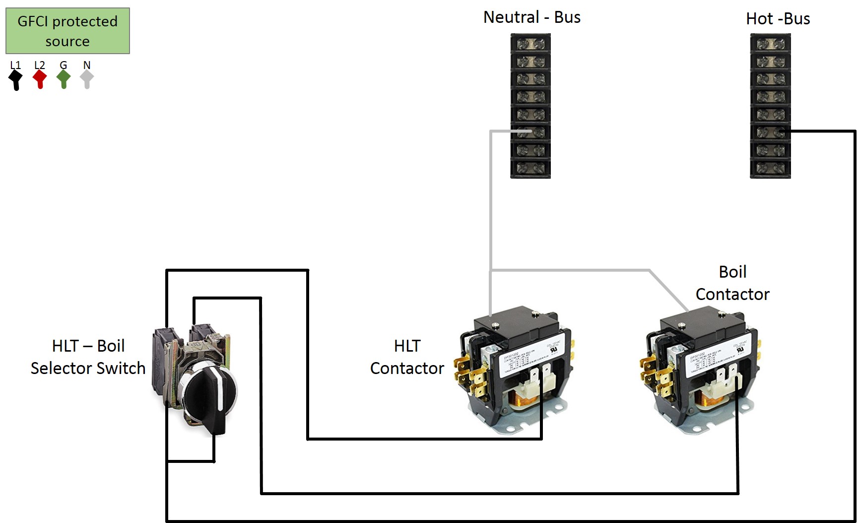
If he did wire like in my instructions, there will be no leaking to the element outlets. If the selector switch is OFF, current can leak to the contactors but no further. So if all is wired they way it should be, there will be no current on the receptacles when the selector switch is in OFF position.
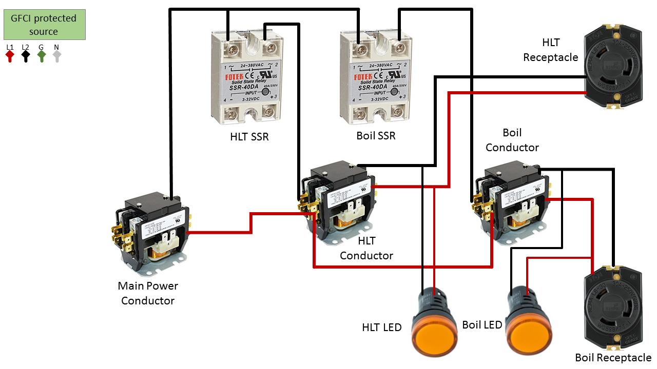
Yeah, I was still thinking about another brewer's testing where they thought that the SSR wasn't turning off when it should. As you say, with a selector controlling contactors, there can be no leakage if wired correctly.
Brew on

")