OP
OP

@LBussy Continuing the topic form the other thread. Im going to go ver your procedures you spelled out in these 2 posts. But at first glance i see it is for brewpi. Would it work the same with fermentrack, before i dig into this??[ETA: In order to "Future-Proof" this article, I have created a page for it on the BrewPi Remix website. You can read the most up to date version there.]
I wanted to share what I think is an easier way to initially setup the HC-05 for BrewPi use. What @day_trippr lined out in the beginning is still valid, however for some people (like me, I'm not ashamed to admit it) "whipping up" a voltage splitter is not necessarily straightforward. It also leverages an Arduino and special sketch to set up the BT device which intimidates some folks. I found a different way that's likely more straightforward for most Windows users.
On Amazon I found a package with an HC-05 Bluetooth Module, a case for that module, Dupont jumpers, and a CP2102 USB to TTL Converter for $12.99 on Prime. That seems like a pretty good deal and provides some pretty good value for a person new to it. When you get a drawer full of "crap", the Dupont wires certainly have less value, but I kinda like the case. So, I'm writing this with that USB to TTL Converter being used:
View attachment 617959
DSD TECH HC-05 Bluetooth Module Kit with CP2102 USB to TTL Converter for Arduino
Buy that ... come back ... now we're ready.
Without further adieu, download some software. You'll probably need the CP2102 drivers, and to follow this you will definitely need the DSD TECH Bluetooth Tools Software. Download and install both of these (actually the "Bluetooth Tools" doesn't install, just unzip to a handy directory):
Don't plug the converter into the USB on your computer yet. Connect the TTL converter and the BT module like so:
View attachment 617962
I actually used the 3.3v the first time, the module will run on 3.3-6v for VIN I believe, but the data channel needs to be 3.3 volts. No worries, the USB to TTL converter handles that for you. Here's the connections in text form:
Converter <-> BT Module
3v3 <-> VIN
TXD <-> RXD
RXD <-> TXD
GND <-> GND
Basically, remember to connect transmit to receive and vice versa. When you are ready and the jumpers are connected properly, connect the device and set programming mode (called "AT mode") by doing the following:
Input low level to PIN34, supply power to the module, input high level to PIN34, then the module will enter to AT mode. Just kidding, I have no idea what that means either. I promised this would be for mortals.
If you have done this correctly, the module should be flashing on and off slowly. Done incorrectly, the device will be flashing rapidly. If you don't get it the first time, unplug the converter and try again.
- Hold the button down on the Bluetooth Module (note about some of the modules sold elsewhere which are insulated with shrink-tube: You may have to cut the tube away from the button in order for it to function correctly)
- Plug in the USB to TTL Converter
- The light will come on for about a second, and then shut off
- Let go of the button on the Bluetooth Module
Now run the "DSD TECH Bluetooth Tools Software" you unzipped. You will be executing "SHTester.exe".
View attachment 617964
To test the device over BT:
- Select the last tab which is "HC-05".
- Drop down the UART box and select the port. On most systems there will be only one. If you have some other COM port device installed there may be more than one listed. If this is the case you will need to open Windows' "Device Manager", look under "Ports (COM & LPT)", and see what COM port is associated with the "Silicon Labs CP210x" device.
- Set Baud Rate to 38400, then click "Open".
- Click the "Test" button, and in the status windows you will see the "AT" command being sent and "OK" received. This will not work unless you are in AT mode (slow flashing). If you don't get anything back it's likely a Baud Rate mismatch. Click on "Close", select a different Baud Rate, "Open" and try testing again till you get an "OK" back.
- Now set "Bluetooth Name" to whatever you'd like it to be, Baud Rate to 57600, PIN (really no reason to change this but remember it), and set Role to "Slave". Click "Set" after each change.
- Now "Close" the UART up top again and you can close the app.
Congratulations! You can unplug the device now, it's ready to be connected to your Arduino.
- Unplug the USB dongle and unplug the two TX and RX wires.
- Plug it back in and now the Bluetooth Module will be flashing rapidly indicating it's ready to be paired.
- Open the Windows Bluetooth settings and click "Add a device."
- Select the name you gave the module above and enter the PIN you used.
- Click "Connect" and if successful, the device will flash briefly every two seconds or so.
So this is where you can go a couple different ways. In order to connect you do need to use a voltage splitter so that the voltage on the communications circuit does not burn out. If you are using @CadiBrewer's shield, this is handled for you. Connect as follows:
Shield <-> BT Module
TXD <-> RXD
RXD <-> TXD
GND <-> GND
VCC <-> VIN
If you are going all rogue and want to do it without a shield, at least you were able to skip the whole Arduino sketch setup thing. You will need:
Wire them according to this diagram which @day_trippr shared in the beginning so that the voltage into the RXD pin on the module is cut to 3.3v:
- 1 x 1K ohm resistor (1/8W axial)
- 1 x 2K ohm resistor (1/8W axial)
- Dupont jumpers
View attachment 617965
The rest of the configuration is in this post above.
@LBussy Continuing the topic form the other thread. Im going to go ver your procedures you spelled out in these 2 posts. But at first glance i see it is for brewpi. Would it work the same with fermentrack, before i dig into this??
Ok i have the box all hooked up and ready to install it. Im reading your manual right now. and from what i see, ill need to setup the HC-05 device first, then connect the controller to the pi and used the Manual workflow setup. I will guess i need to follow LBussy's instructions but use fermentrack's manual work flow. If you have any words of advice or anything, let me know. You have a "Todo" marker to rewrite the manual workflow section, so im shooting from the hip.Yep, you just might need the manual workflow to specify the serial port by hand.
I'm going from memory and it has been a couple of years, so cut me some slack if I remember this incorrectly, but...when I set one of my minions up via bluetooth, it was rather straightforward. Use the automated workflow and get your device working through the normal USB approach. Once it is connected and talking to the Fermentrack software, go through the steps to get the HC-05 programmed. Wire it to your board. Then go into the manage device/view logs tab for that device in Fermentrack and change the port from dev to whatever rfcomm port you assigned during the HC-05 setup when you bound it to the Pi. Should work as expected.Ok i have the box all hooked up and ready to install it. Im reading your manual right now. and from what i see, ill need to setup the HC-05 device first, then connect the controller to the pi and used the Manual workflow setup. I will guess i need to follow LBussy's instructions but use fermentrack's manual work flow. If you have any words of advice or anything, let me know. You have a "Todo" marker to rewrite the manual workflow section, so im shooting from the hip.
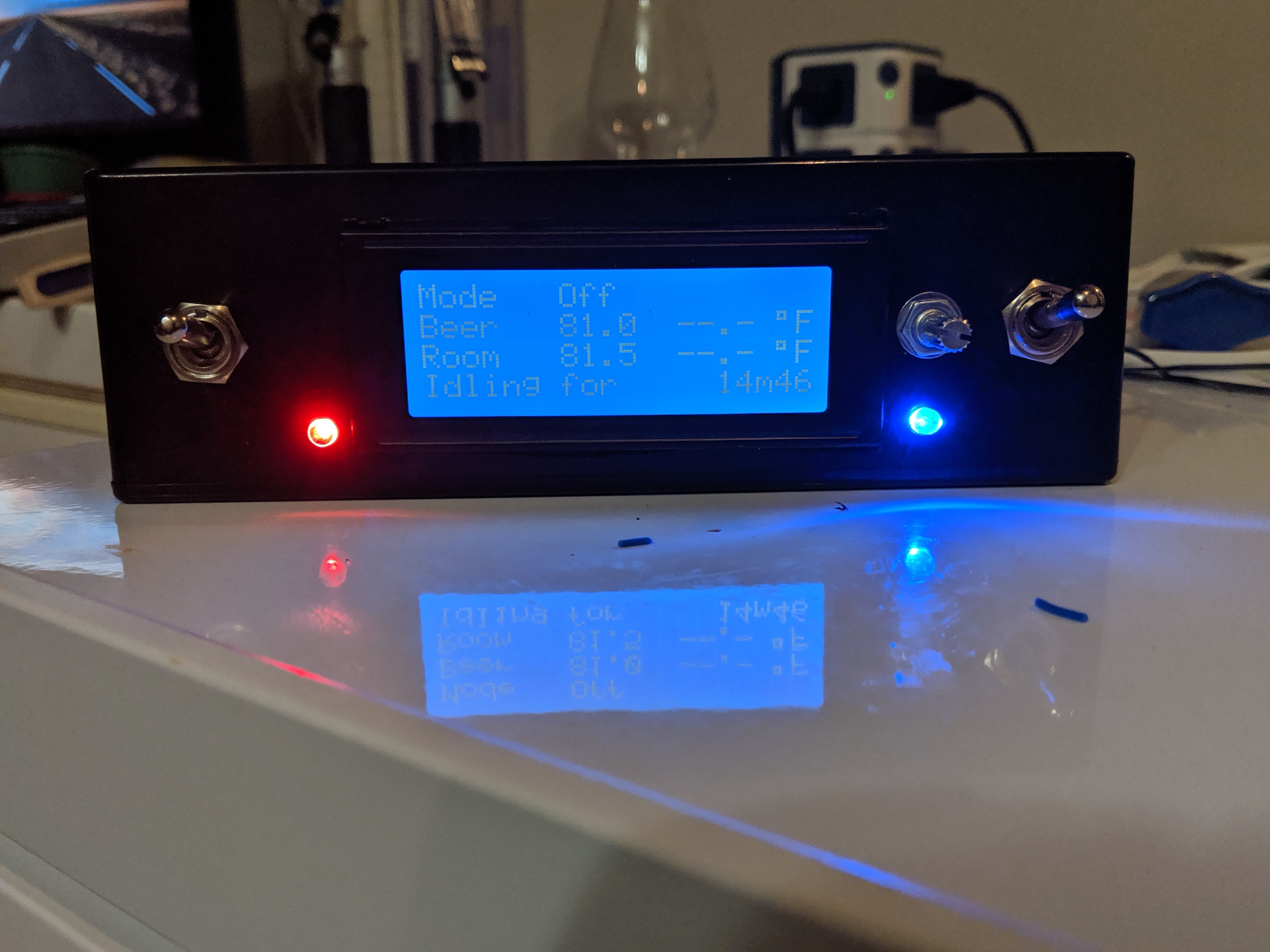
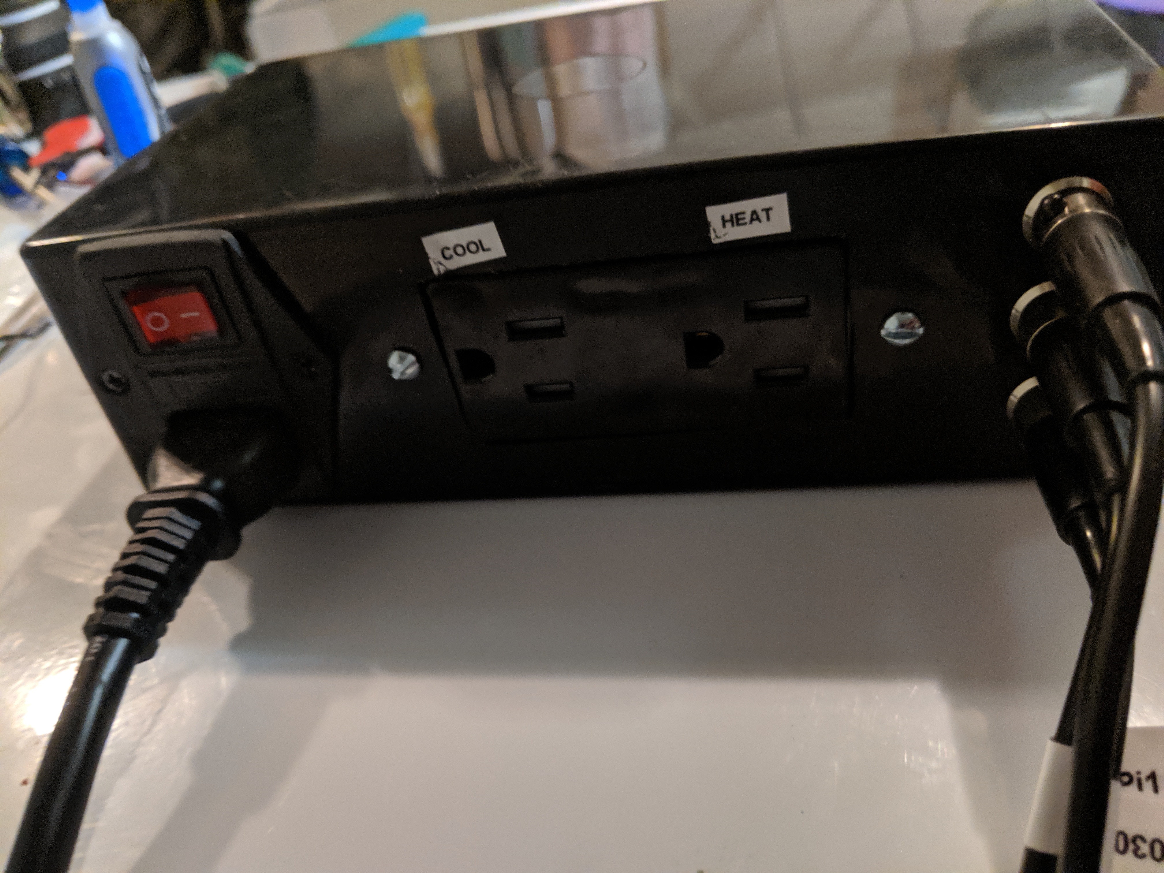
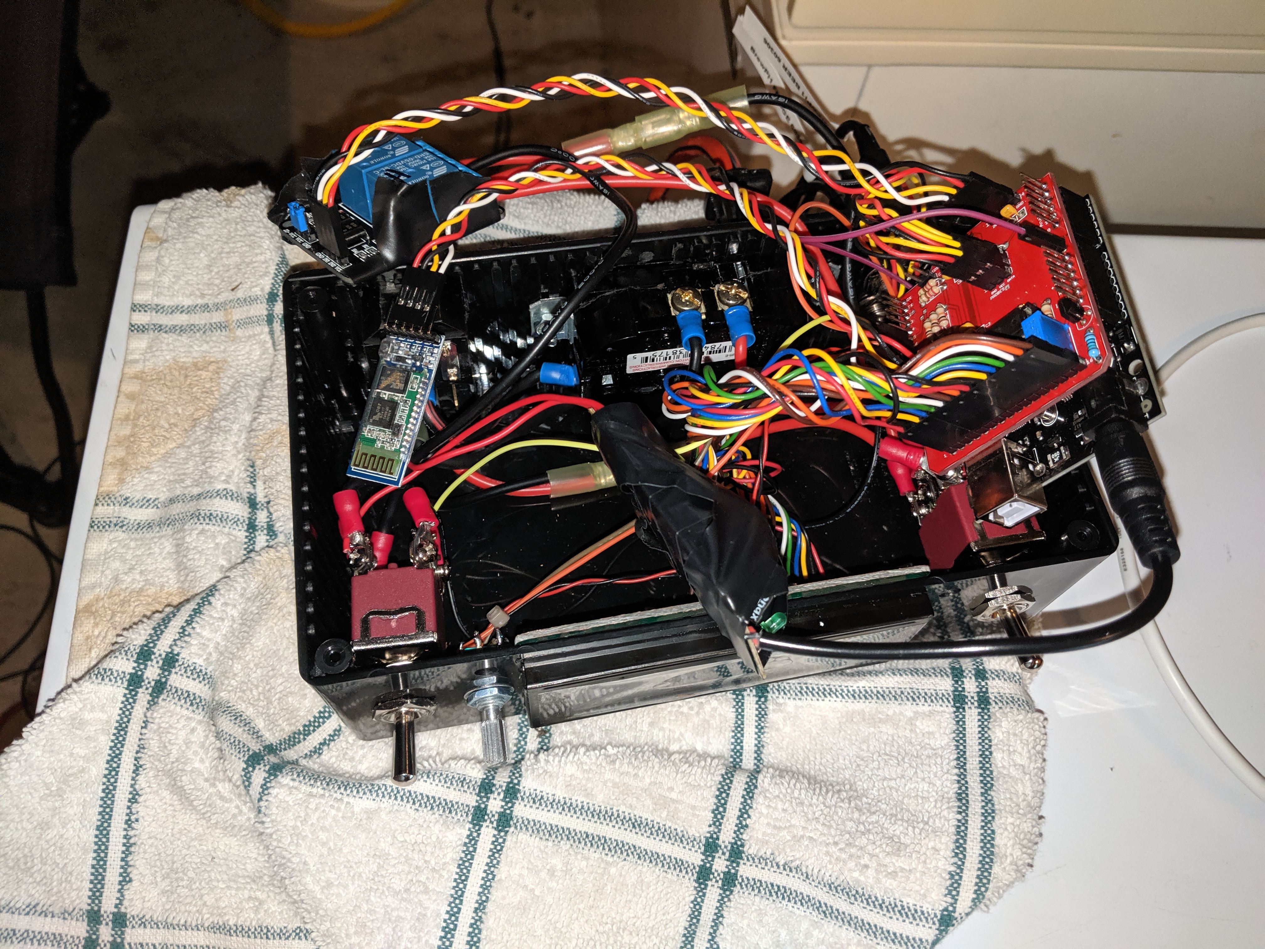
I forgot to take a pic last night but im using a project box like yours and damn..... i should have heeded your warning about it being a huge task to get everything to fit in there. I mean i did it, kinda, but is is PACKED! Im giving my self a win on this but it isnt too pretty in there. And i still havent wired the LEDs yea. Still trying to figure out how to mount them to the box. i have another one to build so im thinking of finding a bigger box to put this in.DAYAAAMMM!
Man if it is that straight forward im going to be so happy!! i might build my 2nd one in this box.I'm going from memory and it has been a couple of years, so cut me some slack if I remember this incorrectly, but...when I set one of my minions up via bluetooth, it was rather straightforward. Use the automated workflow and get your device working through the normal USB approach. Once it is connected and talking to the Fermentrack software, go through the steps to get the HC-05 programmed. Wire it to your board. Then go into the manage device/view logs tab for that device in Fermentrack and change the port from dev to whatever rfcomm port you assigned during the HC-05 setup when you bound it to the Pi. Should work as expected.
")
Enter your email address to join: