Hoosierbilly
Well-Known Member
I don't have access to 220/240v where I brew, I mostly brew using 2 elements on different circuits and have been for some time now. Every now and then I will do a larger brew (up to 2 bbl) using my stout tanks and gas, but mostly I am doing 10gal batches with electric. I currently have 4 elements (2 in HLT and 2 in BK) and have been plugging in/unplugging them to switch from mash and boil and running pumps using a power strip with an on/off switch. I am making the move to motorized ball valves and trying to devise a control panel to allow for very little hands on manipulation throughout the brewing process (valve turning, kettle lifting, cleaning MT to use at BK, element swapping, hose swapping, cleaning spills, tending to burns, all that fun stuff, etc.)
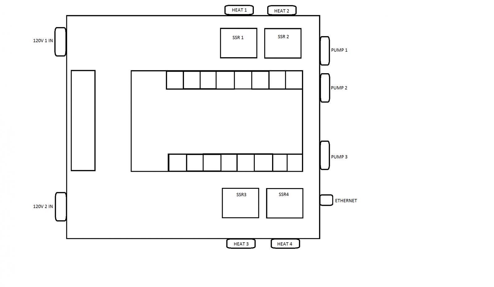
So I'm working with two 120v 20a circuits in my garage and I am trying to sort out my control panel. Here is an initial planning, the picture just shows which circuit will control what. Black is one circuit, blue is from the other circuit.
I will be using my single tier HERMS setup with a BCS 462, 4 2000W elements (only 2 at a time will be used, 1 from each 20a circuit), and 3 march pumps (pumps 1 and 2 running during mash, only pump 3 during the end of boil/chilling) and around 10 motorized 12v ball valves.
My last control panel was very simple: BCS460-->two relays-->two outlets for elements. This one will be more complicated and it sounds like I should have contactors and some redundant safeties that were not in my last CP.
Questions I have right now are:
1. Starting with the main power switch, would I need two separate switches (one for each circuit) or is there a contactor than can switch both 120v circuits simultaneously, or can one switch control two contactors? And could I have the main power switch/switches act as the Estop (but keep power to the BCS) or should I have a separate Estop. From what I see the Estop flips the GFCI which would stop everything, including power to the BCS.
2. As far as only allowing power to one element per circuit, it looks like most people use a 3 position selector switch (HLT-OFF-BOIL). Is there anything wrong with having that selector switch control 4 DPDT contactors that are connected to the 4 SSR's that power the elements (instead of two DPDTs in most panels)?
3. With having 4 or 5 different devices powered from each circuit I'm assuming I will want to have a hot bus, neutral bus, and ground bus for each 120v circuit an have each component connected to these?
4. I have 5v and 12v wall adapters for the BCS and my 16 ch relay board, I'm not sure how to tie these into the 120v circuits inside the control panel? Do I just wire in a standard 120v 15a female receptacle to plug these into inside the control panel? I assume from a hot bus and neutral bus (the wall adapters are 2 prong)?
Maybe this has been done before on here but I sure as heck couldn't find something like this? Maybe this just simply can't for shouldn't be done? Thanks for any info or insight you might have. You guys are awesome.


