kal
Well-Known Member
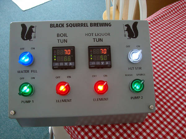
Beautiful stainless panel! Nice work. Amazing how quickly you run out of room isn't it? Mine that I'm working on is 16x16x8 and I'll be using all of it. Yikes.
Kal
Kal

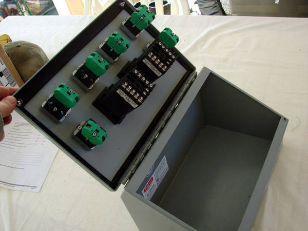
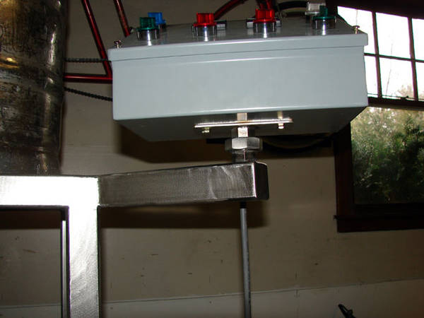
Mike, did you consider punching a hole in the side of the panel at all so that the SSR's sit directly on the heat sinks?
The way you've done is less work of course and was what I was originally going to do, but I'm now considering cutting a hole in the box for better heat transfer to the heatsinks (since there's no extra panel in between).
Kal

") I'll just use them for some other project in the future.... ).
I'll just use them for some other project in the future.... ).I'm not sure how much heat is actually created, it might be overkill. The stainless is not very thick, maybe 18 gauge tops. POL said his just gets warm to the touch. I like that huge heatsink you got there Kal, very nice.
Mike
BrewBeamer: Why not just cut a hole in the enclosure, attach the heat sink to the ensure (with sealer around to make it water proof) and then attach the SSR's directly to the heat sink?
On other words, Why use the thick aluminum plate at all?
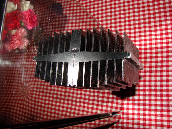
In my case my enclosure is 16x7" at the top and I'm putting this massive 12x7x3" heatsink on the top:
Two SSR's will be attached to it.
($10 off of ebay - half the price of one Auber heat sink but probably 10 times the heat dissipation. Of course, I have two Auber 40A heatsinks that will now go unused since I already bought them too ..... <Sheesh>
Kal
Yah... my little standard heatsink just gets warm to the touch. The thing doesnt get that hot when I am boiling. The standard ones, for those that care, are very sufficient.


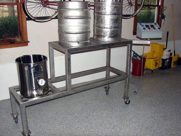
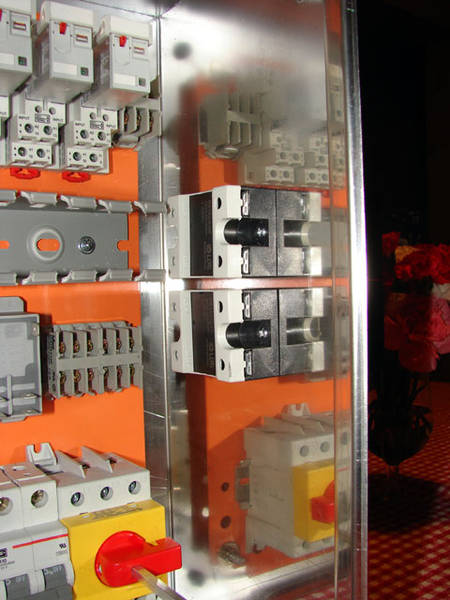
Yea thats them in the side of the electric panel. They are twist lock 30A outlets from HD. Pretty simple install, just drilled the hole with a holesaw and screwed them in place. I did seal them up with some silicone.

What mounting adapters did you use to secure the 22 mm switches to the front plate? I just ordered the same switches and realized I have no idea who sells the mount/adapter.
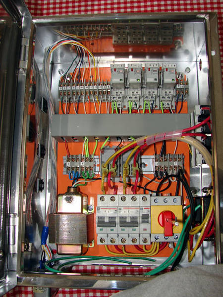
If you look on the third page of the thread there is a basic wiring diagram that might help you out.paddy21 said:Hi,
I'm building a 240V brew kettle.
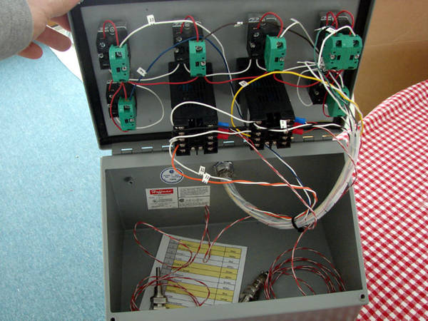
I'm wondering if you have a BOM of your control box or could tell me what is going on with regard to the 240V heating element.
It looks like power comes in through a switch to some GFI fuses (maybe) and then to an SCR. The part I'm a bit fuzzy on is if the red & yellow wires are each leg of the 240V line.
Is this the idea?
Thanks! LOOKS AWESOME btw.
Enter your email address to join: