Contactor rumbling noise!

Homebrew Talk - Beer, Wine, Mead, & Cider Brewing Discussion Forum

Help Support Homebrew Talk - Beer, Wine, Mead, & Cider Brewing Discussion Forum:

This site may earn a commission from merchant affiliate links, including eBay, Amazon, and others.
I made the same mistake with a Packard contactor that I bought from Amazon. Same rumbling noise. Thanks for the info P-J!
 
Yup I just need confirmation of my screw up. Now I'm wondering if I can even use this now.
 
You certainly can use it.

Do you have a wiring diagram for your intended set up? Perhaps I can help.

Thank you P-J
I don't have a diagram for me I kind of used the combination of two. Right now I have it wired up like the first one on this list. In the future I will be adding a second element for the BK which I already have the parts including a second 240volt coil ssr and pid. I have one pump and and 50 amp spa box feeding everything. If you could help me wire it for future I can work with that.
https://www.homebrewtalk.com/f170/list-pj-electrical-diagrams-382286/
 
If you just help me understand how to wire the coil for 240volt I'd be grateful. My assumption is that I could replace the neutral wire with the second hot line, but would my switch be Ok being only rated at 120v.
 
If you just help me understand how to wire the coil for 240volt I'd be grateful. My assumption is that I could replace the neutral wire with the second hot line, but would my switch be Ok being only rated at 120v.
Just replace the contactor coil neutral wire (yellow & on top) with a Line 2 wire (red). The indicator lite on switch 1 still needs to have the neutral.

You could also use the 2nd contact set of switch 1 (terminals 13 & 14) to contral line 2 for the contactor coil.

Edit: The switch is rated for 120V because of the indicator lite.
 
I just fired up the newly-minted Mark II version of my control panel and found that I had made the same mistake as the OP: 240V coil instead of 120V. Duh! Anyway, I'm planning to use what I have rather than replace, so I'll be leading Line 2 to the side of the coil that had the neutral (wrongly) attached. Questions:

-- In another post P-J has a wiring diagram for this where Line 2 comes through the same switch as Line 1. Is this necessary, or can I just run a jumper from where Line 2 goes into the contactor to the coil? (This is for my panel master switch contactor).

-- If that's okay for my main panel switch contactor, can I do the same for my two heating element stitch contactors, i.e. Line 1 comes to the coil from a selector switch from the Line 1 hot bus; Line two comes to the coil of each element contancor as a jumper from the Line 2 in side of each element contactor (Line 2 is daisy-chained from the out side of the panel master switch contactor).

Does this make sense? Wish I were better at diagramming so I could provide a visual ....
 
I would think that you would want to run both hots through the switch, so that when you turn the switch off nothing else in the panel is energized. If you bypass the switch with the second hot, then your panel is live even when your main switch looks off.
 
I would think that you would want to run both hots through the switch, so that when you turn the switch off nothing else in the panel is energized. If you bypass the switch with the second hot, then your panel is live even when your main switch looks off.
shtank,

I agree with jeffmeh and am more than willing to redraw the diagram for you. It is fairly easy for me to do and certainly very easy for you to implement.

Please consider it and let me know.

P-J
 
P-J said:
shtank,

I agree with jeffmeh and am more than willing to redraw the diagram for you. It is fairly easy for me to do and certainly very easy for you to implement.

Please consider it and let me know.

P-J

Thanks P-J (and jeffmeh). I think I'd need another block for my main panel switch to run Line 2 through it (I'm using an Auber SW8). But does it really make things "safer" to run it through the switch? If the Line 2 jumper is just going to the main switch contactor coil, the rest of the panel isn't getting any juice when the switch is off, right? (Not questioning your expertise, just trying to learn).
 
Thanks P-J (and jeffmeh). I think I'd need another block for my main panel switch to run Line 2 through it (I'm using an Auber SW8). But does it really make things "safer" to run it through the switch? If the Line 2 jumper is just going to the main switch contactor coil, the rest of the panel isn't getting any juice when the switch is off, right? (Not questioning your expertise, just trying to learn).
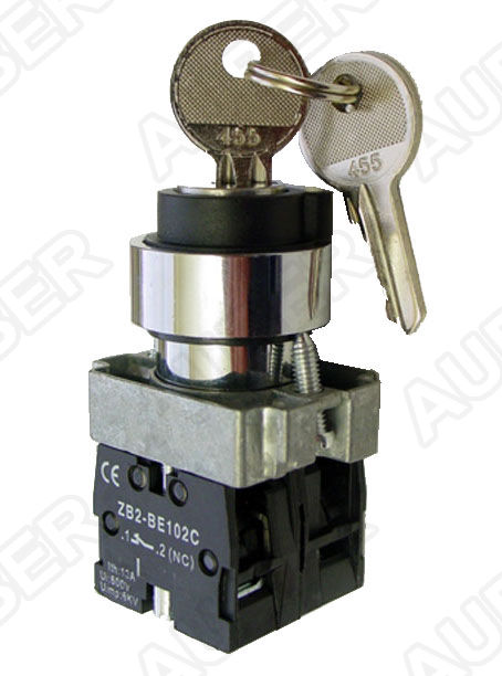
Auber Instruments key switch - SW8

SW8.jpg


has a N/O & a N/C contact set. You will need to add a 2nd N/O contact instead of the N/C block for it to work for your setup. The N/C switch block will not function for a 240V power feed.

If you do not open both legs of the 240V power feed there will be raw power within your controller even when the key switch is off. For me that is a risk too great to over look. Be careful..!

I guess what I'm trying to understand is why it's less safe to run Line 2 direct to the coil, since Line 1 (on the other side of the coil) is open when the switch is off, so there is no completed circuit for the power to run through? Is it because if Line 1 shorts out somewhere along the way it will be a 240V short, not just a 120V short?
 
Completely on a tangent here, but when I started to read your post and saw where you lived, my first thoughts were about what happened to a friend of mine down in Lillington this past summer. This is way the hell off topic, but sort of amusing and I am buzzing and talkative. :D

His system just stopped working one day. Prior to it just flat out ceasing to function, one of his contactors had been rumbling when it was on, but now it was just completely dead, so he put out the 911 call for me to help. I drove my ass 1 hour down to his place one evening to work on the issue.

Within 10 minutes, I figured out that the main "SYSTEM ON" switch that controls power to all of the other panel controls seemed to be dead. Without that thing not passing current through, the other switches for the individual components, the lights, the PIDs, etc, etc couldn't do anything. I bypassed that main switch and verified that everything was workingl and we dropped in a new switch. Everything was hunky-dorey and his system was alive again.

I wasn't about to spend 2 hours round-trip driving to fix his problem in 10 minutes, so I sat my ass down in his garage to drink a couple beers and shoot the breeze.

Out of curiosity while chatting, I pried open the faulty switch to see what had happened to it, and my brain couldn't immediately process what I was seeing. The body of the switch looked like it was packed full of brown sugar.

Looking closer, that brown sugar was actually a solid brick of dead fire ant bodies.

I did some googling and found out that fire ants have some seriously potent pheromones that they use to communicate with each other. It turns out that if you electrocute a fire ant, it will blow its pheromone wad in a big way. This attracts more fire ants to the same location, who will also be electrocuted, and who will also blow their wad, which attracts more fire ants to the same location, who also get electrocuted, who...... yadda yadda yadda.

Eventually, this death cycle only stops when no more ants can fit into the place where they are all being killed. Hence the solid mass of dead ants inside the switch. The switch could no longer actually make contact when you flipped it on because of the pile of bodies in the way.

Anyway... now that I talked your ear off about absolutely nothing, I'm going to get a beer.
 
I guess what I'm trying to understand is why it's less safe to run Line 2 direct to the coil, since Line 1 (on the other side of the coil) is open when the switch is off, so there is no completed circuit for the power to run through? Is it because if Line 1 shorts out somewhere along the way it will be a 240V short, not just a 120V short?

If both hots run through the switch, then when the switch is open only the switch is energized.

If only one hot runs through the switch and the other runs directly to the main power contactor coil, then when the switch is open the switch is energized, and the contactor coil has a hot line that would give you 120v to neutral or ground. Let's say in a worst case scenario the wire really does make contact with neutral, you now have 120v in the panel when your main power switch reads off.

Scenario 2 is clearly less safe than scenario 1. Is it likely to cause a problem? Not likely, unless you decided to open your panel with it plugged in, which is a bad idea even with a main switch. Is it bad practice? Yes. A "main power off" switch should cut all power in the panel beyond the switch, not "except there is still 120v in there." :)
 
I'm not sure I agree with P-J and jeffmeh here (which likely means I'm wrong as we often agree).

Say you run Hot A from your supply to the line side terminal of the contactor and jumper it to the coil. You run Hot B from the supply to the second line side terminal of the contactor, and then jumper from there to a NO switch and then to the coil. There are no other connections 'upstream' of the contactor.

With the switch off, you have power to the line side of the contactor (both termianls), to half the coil (hot A), and to the NO contact on the switch (Hot B). There is no path for the power to go to neutral or ground and thus derive 120v. It's an open circuit, and the coil has 0v.
 
BadNewsBrewery said:
I'm not sure I agree with P-J and jeffmeh here (which likely means I'm wrong as we often agree).

Say you run Hot A from your supply to the line side terminal of the contactor and jumper it to the coil. You run Hot B from the supply to the second line side terminal of the contactor, and then jumper from there to a NO switch and then to the coil. There are no other connections 'upstream' of the contactor.

With the switch off, you have power to the line side of the contactor (both termianls), to half the coil (hot A), and to the NO contact on the switch (Hot B). There is no path for the power to go to neutral or ground and thus derive 120v. It's an open circuit, and the coil has 0v.

Yeah, that's kind of the way I'm looking at it. But since I'm not an EE or anything close, I'm going to go with the "conservative" approach and run both hot leads through the master switch (already ordered another NO block for it!). To me, though, from a purely logical point of view, it seems like the risk of one of the hots completing a circuit with neutral, ground or the other hot is no less likely using either approach. In fact, I personally view running additional hots to the front panel to be something that increases risk, if only marginally (I was originally planing to keep Line 2 off of the front panel entirely, but the design changes required by my mistaken purchase of the 250V coil versions of the contactors kind of scotched that plan anyway).

As always, I appreciate that we can discuss matters like this on this forum, and the willingness of smart people to share their knowledge with me! Thanks guys!
 
Walker said:
Completely on a tangent here, but when I started to read your post and saw where you lived, my first thoughts were about what happened to a friend of mine down in Lillington this past summer. This is way the hell off topic, but sort of amusing and I am buzzing and talkative. :D

His system just stopped working one day. Prior to it just flat out ceasing to function, one of his contactors had been rumbling when it was on, but now it was just completely dead, so he put out the 911 call for me to help. I drove my ass 1 hour down to his place one evening to work on the issue.

Within 10 minutes, I figured out that the main "SYSTEM ON" switch that controls power to all of the other panel controls seemed to be dead. Without that thing not passing current through, the other switches for the individual components, the lights, the PIDs, etc, etc couldn't do anything. I bypassed that main switch and verified that everything was workingl and we dropped in a new switch. Everything was hunky-dorey and his system was alive again.

I wasn't about to spend 2 hours round-trip driving to fix his problem in 10 minutes, so I sat my ass down in his garage to drink a couple beers and shoot the breeze.

Out of curiosity while chatting, I pried open the faulty switch to see what had happened to it, and my brain couldn't immediately process what I was seeing. The body of the switch looked like it was packed full of brown sugar.

Looking closer, that brown sugar was actually a solid brick of dead fire ant bodies.

I did some googling and found out that fire ants have some seriously potent pheromones that they use to communicate with each other. It turns out that if you electrocute a fire ant, it will blow its pheromone wad in a big way. This attracts more fire ants to the same location, who will also be electrocuted, and who will also blow their wad, which attracts more fire ants to the same location, who also get electrocuted, who...... yadda yadda yadda.

Eventually, this death cycle only stops when no more ants can fit into the place where they are all being killed. Hence the solid mass of dead ants inside the switch. The switch could no longer actually make contact when you flipped it on because of the pile of bodies in the way.

Anyway... now that I talked your ear off about absolutely nothing, I'm going to get a beer.

Great story. Makes me glad I live in MN! (Is it just a coincidence that everyone else posting on this thread is from NC?) As I recall, you and I were working on our original control panels at the same time, a couple of years ago. Glad to see neither of us was zapped by our efforts.
 
I'm not sure I agree with P-J and jeffmeh here (which likely means I'm wrong as we often agree).

Say you run Hot A from your supply to the line side terminal of the contactor and jumper it to the coil. You run Hot B from the supply to the second line side terminal of the contactor, and then jumper from there to a NO switch and then to the coil. There are no other connections 'upstream' of the contactor.

With the switch off, you have power to the line side of the contactor (both termianls), to half the coil (hot A), and to the NO contact on the switch (Hot B). There is no path for the power to go to neutral or ground and thus derive 120v. It's an open circuit, and the coil has 0v.

Now I'm getting confused, lol. Let's see if I can sort it out.

We are discussing thas the use of a single NO switch to turn on/off power in the panel, through the use of a NO DPST mechanical contactor.

Whether the contactor coil is 120v or 240v, in each case both Hot A and Hot B must run from the supply to the line side terminals of the contactor (and of course, out from the load side).

If said contactor has a 120v coil, a typical wiring would be running Hot A from the line side of the contactor, through a switch, then to the contactor coil, and to wire neutral to the other side of the coil.

The question is, if said contactor has a 240v coil, should Hot B be wired similarly (from the line terminal, through an additional NO contact block on the switch, then to the contactor coil)? Alternatively, would it be reasonable to not use the switch, so that Hot B runs directly from the line side terminal to the contactor coil?

Let's count the hot wires, when the main switch is open.

With both hots going through the switch, there are two at the switch and two at the line terminals of the contactor.

With only Hot A going through the switch, there is one at the switch, two at the line terminals of the contactor, and one at the Hot B coil terminal of the contactor.

I still prefer both hots through the switch, but I concede that it makes little difference.
 
Do you agree there's no way for the coil to get 120v with 1 Hot leg and 1 open hot leg from the switch? Barring, of course, some annomoly where wiring comes lose or somethign shorts out.

I, like the OP, tried to minimize my hot wire runs before the contactor. So while in both scenarios there are 4 points that have live terminations, in the single switched leg, you only have 1 wire running to the front of the panel, whereas in the double NO / both legs switched, you have a second wire running up to the front. Probably not a big deal as you odn't open / close the cover much after the panel is finished - just a difference.
 
I think the concern wasn't about the something running at 120V, but was more about having a wire energized at the kettle. No current is flowing because it has no where to go, but if you decided to work on it with the element switch turned off, you could still zap yourself because one of the wires was hot.
 
Do you agree there's no way for the coil to get 120v with 1 Hot leg and 1 open hot leg from the switch? Barring, of course, some annomoly where wiring comes lose or somethign shorts out.

I, like the OP, tried to minimize my hot wire runs before the contactor. So while in both scenarios there are 4 points that have live terminations, in the single switched leg, you only have 1 wire running to the front of the panel, whereas in the double NO / both legs switched, you have a second wire running up to the front. Probably not a big deal as you odn't open / close the cover much after the panel is finished - just a difference.

I do agree. In the case of a short or a loose wire anomaly, all bets are off in either scenario.

Do you agree that, while it is highly unlikely for an anomaly to occur that would close the contactor if the coil has one live termination, it is even less likely if the coil has no live terminations?

Again, in practical terms I don't see much difference at this point. Cheers.
 
jeffmeh said:
Now I'm getting confused, lol. Let's see if I can sort it out.

We are discussing thas the use of a single NO switch to turn on/off power in the panel, through the use of a NO DPST mechanical contactor.

Whether the contactor coil is 120v or 240v, in each case both Hot A and Hot B must run from the supply to the line side terminals of the contactor (and of course, out from the load side).

If said contactor has a 120v coil, a typical wiring would be running Hot A from the line side of the contactor, through a switch, then to the contactor coil, and to wire neutral to the other side of the coil.

The question is, if said contactor has a 240v coil, should Hot B be wired similarly (from the line terminal, through an additional NO contact block on the switch, then to the contactor coil)? Alternatively, would it be reasonable to not use the switch, so that Hot B runs directly from the line side terminal to the contactor coil?

Let's count the hot wires, when the main switch is open.

With both hots going through the switch, there are two at the switch and two at the line terminals of the contactor.

With only Hot A going through the switch, there is one at the switch, two at the line terminals of the contactor, and one at the Hot B coil terminal of the contactor.

I still prefer both hots through the switch, but I concede that it makes little difference.

Hi jeffmeh, thanks for articulating my issue so well. I was worried that there was something about contactors that I didn't understand. IMHO, the "loose wire" scenario plays out about the same, whether you run Line 2 through the switch or not. Right now I'm just happy because I can use my 250V coil contactors and don't need to pull my panel apart to swap them for 120V. Having just hung it on the wall and tidied things up inside, that's something I'm really glad to avoid! Plus, I fired it up for the first time last night, and darned if the thing doesn't work!!!
 
Walker said:
I think the concern wasn't about the something running at 120V, but was more about having a wire energized at the kettle. No current is flowing because it has no where to go, but if you decided to work on it with the element switch turned off, you could still zap yourself because one of the wires was hot.

Yeh, but the hot lines in to the contactor from the service are exposed in any event, so you could get yourself zapped no matter how you wire the coils. Bottom line: unplug the panel when it's open. Problem solved!
 
I think the concern wasn't about the something running at 120V, but was more about having a wire energized at the kettle. No current is flowing because it has no where to go, but if you decided to work on it with the element switch turned off, you could still zap yourself because one of the wires was hot.

Whether you have 1 switched wire to the main contactor coil, or 2, there will never be a situation (barring the abnormal / errors) where the coil will be closed and 120v and an energized wire at the kettle. I think you're confusing the main contactor we're talking about with something else.

Do you agree that, while it is highly unlikely for an anomaly to occur that would close the contactor if the coil has one live termination, it is even less likely if the coil has no live terminations?

I agree 100% - fewer live terminations at the coil decreases the risk of some anomaly causing errors at the contactor. But, as we've pointed out, the risk is so low that it's a non-issue either way.

Again, in practical terms I don't see much difference at this point. Cheers.

Yup - wire it up either way, he'll have a functional and safe panel!

-Kevin
 
I'm pleased to hear that it is all working out for you. And it appears that Kevin and I are in violent agreement yet again. :)
 

Latest posts

Back
Top