BruControl: Brewery control & automation software

Homebrew Talk - Beer, Wine, Mead, & Cider Brewing Discussion Forum

Help Support Homebrew Talk - Beer, Wine, Mead, & Cider Brewing Discussion Forum:

This site may earn a commission from merchant affiliate links, including eBay, Amazon, and others.
Great points here. It would definitely be a PITA to drag a desktop outside! I suppose it would be better to use a laptop, of if another remote computer were doing the control work, you could use a tablet with screen sharing (this is what I do and it works well - a PC inside runs BC and I used an RDP app on my iPad in the garage). In the next iteration we will have a web interface so that it another display avenue.

You could certainly run with dedicated control hardware, though I think it would hold you back from your brewery's potential. To just display two or three numbers would be limited. Are you saying you do not want to have any screen/monitor at all? How many 7-segment displays do you have?

If you would like to discuss live, PM me and I will reply with my cell.

Do you still plan on adding a web interface? That would be great, Amazon tablets are very cheap and could be used for remote access throughout your home.
 
Hi @Kmo4040... we will do that eventually, but it is not slated for the v1.1 release. We have some other things to accomplish first. It may be the sole effort for 1.2. In the meantime, use remote access software like Windows Remote Desktop, Teamviewer, or Chrome Remote Desktop.
 
I've got an idea, actually I had this idea a long time ago and haven't implement it, sorry if I've already brought it up for discussion and forgot about it. Does your scripting feature allow for the following behavior: on the fly, dynamic boil intensity and/or boil time to achieve a target gravity and/or post boil volume?

The idea is that before starting the boil you would input your measured preboil gravity and target og, the the system could then read volume levels via pressure sensors and calculate how much water needs to be boiled off to achieve OG and estimate boil time. It would periodically check the volume during the boil and adjust boil intensity (or boil time) as necessary.

Is this something I could achieve with your scripting interface?
 
Neat idea! Yes, the script could do it. Assuming you know the starting gravity and some basic performance parameters (boil off rate at different boil powers), using the volume (pressure or other means) sensor you could have the boil end on a specific OG by changing the boil intensity. You wouldn’t necessarily want to change the boil time as that would impact hop isomerization.
 
Anyone care to share their panel wiring diagrams for a BruControl setup? I've seen a number of BCS panel diagrams based on the BCS-462 which I assume could be a good starting point by replacing the 462 with an Arduino board, with maybe some minor modification. However, some of you guy's panels, at least externally, eliminate most of the manual/analog switches and indicators that you find on a typical BCS panel (like the panels from Electric Brewing Supplies). I'd like to start off using BruControl simply as a digital version of an analog brew panel with basically no automation but not sure if all the switches, indicators, and internal electrical components of a BCS panel are really necessary. Any suggestions?
 
I need to apologize for not getting some brewery schematics up on the website. Part of the issue has been [excuse coming] that I had been unable to find a decent drawing program which had a reasonable library of schematic parts and was not going to be costly. I finally solved that and got some fermenter schematics up, but the brewery examples have been lagging.

You are correct in that they are basically interchangeable as both the digital inputs and outputs are active high, 5V logic.

With respect to physical switches, including them or not is a personal decision. I personally think they are unnecessary, add additional cost, require additional space, require extra labor to build in, etc. My current “control panel” (in my build thread) is a roughly 10” x 2 x 2” enclosure and houses the power switch, power LED, E-stop, 2x element LEDs, and alarm LED/buzzer. You could go without the alarm as BC has built-in audio, though I don’t think is a bad idea to have a back-up physical alarm in case the computer sound is turned down. You could eliminate the power LED if you had some other indication that the power is on, such as your computer monitor. You could also ditch the element LEDs, though you would not necessarily catch fast updates such as during a PID on/off cycle on screen - the LED makes power on periods very clear no matter how quickly they occur.

Hopefully that helps, but if not I am happy to address any questions or concerns.

I agree that switches aren't strictly necessary, but I think a lot depends on your setup and how fast you can react to issues.

If your computer screen is a touch screen and within arms reach of your rig, then switches may not be needed. However, if you are using a mouse and keyboard which is a decent distance from the rig (to avoid water...), then a switch to shut off the heaters/pumps/etc. in a hurry is a really good idea. I've had to kill the power quickly to avoid a boil over, prevent dry firing an element, etc. more than I'd care to admit. Switches are a good insurance policy against that.

Brundog, what drawing program did you settle on?
 
Yep... personal preference!

I agree than an emergency situation should be handled quickly. My approach (which I would recommend for a BC rig) is to use a key switch to power the entire rig (switches the main contactor). This powers the L1 and L2 bus, which feeds the low voltage power supply which powers the BC interface micro-controller. So as long as the key switch is on, so is the interface. Those buses also feed the contactors which switch high power devices. In my rig I have three: 1 for each element and 1 for the pumps , alarm, and high voltage outlets. These are switched by the E-stop, therefore for the elements or pump will not run unless the E-stop is clear. So in an emergency, slamming the E-stop halts high voltage power devices, but control is maintained. This way the situation can be remedied, then high voltage power restored.

I know many like to use the key switch and E-stop inline. I personally feel this is superflous, but I can appreciate the desire for a button to kill power but the switch to lock it out. I do however believe killing control power with the E-stop is poor technique, and must make correction a real PITA. This design type removes the need for switches, but you can always include them as manual overrides if you like. One guarantee with electric brewing, especially automated versions, is **** will go go unexpectedly south every now and again, no matter how careful you are!

I found draw.io suits my purposes well. It was recommended by a member here, and its great being online (or downloadable), free, and a decent library. I also like DigiKey's schemit, which is browser based, but the library is more limited. I was trying to use Fritzing but the library for our generic parts sucks. I just tried gliffy but it is similar to draw.io without the library and is not free. SmartDraw and Visio are good, but they cost ~$200.
 
Here is the schematic for my rig. It hasn't been updated to reflect some non-relevant changes like BCS -> BC. I will draft a proper brewery schematic per above soon, and will create 30A and 50A versions... promise!

BIG FAT DISCLAIMER: This schematic was made by me for my rig and not meant to be a public offering. I am happy to share it but please understand I make no guarantees or claims and cannot/will not be responsible for its interpretation or use by any third parties (aka you!). Please have your own work approved by a qualified technician!

BD-50A-BCS4 (2).png
 
Yep... personal preference!

I agree than an emergency situation should be handled quickly. My approach (which I would recommend for a BC rig) is to use a key switch to power the entire rig (switches the main contactor). This powers the L1 and L2 bus, which feeds the low voltage power supply which powers the BC interface micro-controller. So as long as the key switch is on, so is the interface. Those buses also feed the contactors which switch high power devices. In my rig I have three: 1 for each element and 1 for the pumps , alarm, and high voltage outlets. These are switched by the E-stop, therefore for the elements or pump will not run unless the E-stop is clear. So in an emergency, slamming the E-stop halts high voltage power devices, but control is maintained. This way the situation can be remedied, then high voltage power restored.

I know many like to use the key switch and E-stop inline. I personally feel this is superflous, but I can appreciate the desire for a button to kill power but the switch to lock it out. I do however believe killing control power with the E-stop is poor technique, and must make correction a real PITA. This design type removes the need for switches, but you can always include them as manual overrides if you like. One guarantee with electric brewing, especially automated versions, is **** will go go unexpectedly south every now and again, no matter how careful you are!

This is quite helpful. However, in trying to mentally correlate your description with a BCS462 diagram that I printed out, I get the 2 contactors for the elements, but not the one for the pumps. Perhaps I'm being pedantic on the use of the term "contactor", and I'm not trying to be difficult but I'm a visual learner so the "picture" is everything to me.

1. For the pumps, could you use skip the contactor and rely on a SPDT relay board?
2. Do you have SSRs inline with your element contactors?


EDIT: You posted your diagram while I was typing my questions above so they are pretty much answered except could you describe what is plugged into each of the 120v outlets?
 
Relay = contactor. I would like to see the term contactor go away, but just assume they are synonymous. Or more technically correct, a single pole contactor is a SPST relay, and a dual pole is a DPST relay.

I have one 120V outlet powered full time. It powers a power strip which feeds my overhead LED light, the touch monitor, the mini-PC, and the Wi-Fi bridge. The switched outlets power the pumps, the overhead fans (not needed anymore with the steam condenser) and the fountain pump for my secondary chiller.
 
I agree that switches aren't strictly necessary, but I think a lot depends on your setup and how fast you can react to issues.

If your computer screen is a touch screen and within arms reach of your rig, then switches may not be needed. However, if you are using a mouse and keyboard which is a decent distance from the rig (to avoid water...), then a switch to shut off the heaters/pumps/etc. in a hurry is a really good idea. I've had to kill the power quickly to avoid a boil over, prevent dry firing an element, etc. more than I'd care to admit. Switches are a good insurance policy against that.

Brundog, what drawing program did you settle on?
For this reason alone I have a kill switch that will kill the pump and element power only on my panel. (ironically its the emergency stop and works the same way as brundogs setup only mine kills the 24v line which powers all my relays and pumps).. as well as the amp/power meter to monitor if something is on and drawing power.

Honestly the only time I miss my manual analog controls is when controlling my pwm DC pumps whether on /off as well as speed... The touchscreen or mouse is just not the same as the knob and switch as far as speed and the pump runs dry more this way... I know Brundog talked about having the ability of an easy on/off switch as well as a popup speed keypad and those would help tremendously for this but im not sure enough people are using this application to justify it.

Just my 2 cents but as far as using relays on top of the ssrs I think those are justified myself to avoid failed ssrs being stuck on. It also gives me that easy on off quick control (which I could wire my pumps up to utilize as well and may do so now that I think about it.) and it prevents me from accidentally firing my 5500w element at the same time as my rims or HLT while allowing those two to be on at the same time.
 
Just my 2 cents but as far as using relays on top of the ssrs I think those are justified myself to avoid failed ssrs being stuck on. It also gives me that easy on off quick control (which I could wire my pumps up to utilize as well and may do so now that I think about it.) and it prevents me from accidentally firing my 5500w element at the same time as my rims or HLT while allowing those two to be on at the same time.

I've also seen at least one diagram (who's escapes me the moment as I've been looking at a bunch) with a safety interlock 8-pin relay wiring scheme that won't allow you to activate the main power contactor via the key switch unless the element and pump switches (3-way switches) are in the OFF position. That would guard against turning the system on and having components, like elements, turn on at the same time.
 
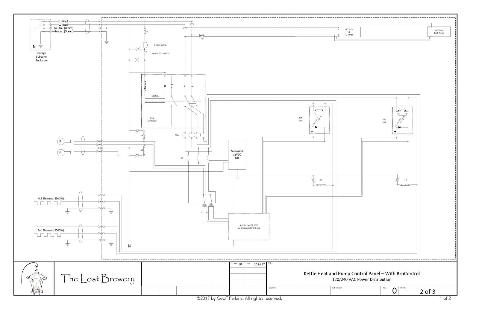
@BrunDog I use Visio, and spent some time building a component library. Here's the latest iteration of the power distribution side. Still need to do a low-voltage diagram.

Schematic.jpg
 
Happy Halloween! We have posted BruControl version 1.0, build 28084 and firmware v42M. Please download these from the website links at BruControl.com. The application software and firmware must be used together! The application, firmware, User Manual, and Interface Wiring Maps have been updated (wiring options have not changed however, so no re-wiring is required).

List of changes:
  • Added: One-Shot option for digital outputs, Arduino Primo support, back-light and clear control functions for local LCD displays, gateway and subnet configuration options for default network connections, buzzer tones in Primo, control codes for default network connections. Note: Primo firmware currently supports communication with TILT hydrometers, though this version of BruControl does not yet.
  • Changed: Network interfaces communicate via serial (USB) also, default network setup is now handled via "control code" rather than during interface boot-up (no on-board LED flashing either).
  • Fixed: Serial (USB) connection's buffer overload during high overhead I/O execution periods, Ethernet disconnection over Wi-Fi bridge inability to reconnect, script deletion during application restart, data log missing, multiple bug fixes.

For those upgrading:
  • Make a copy of your individual scripts. In BruControl's script editor, use Ctrl+A to select the entire script text, then use Ctrl+C to copy it to the clipboard. Open Notepad or other non-formatting text editor, then paste the script and save the file in the folder of your choice.
  • Close BruControl. Since you will be updating the firmware, you will need to make sure your machinery can be disabled for a while.
  • Make a backup copy of your user files. These are located in Documents/BruControl. You can select the entire folder, copy it, then paste it as a copy.
  • Update the firmware using the Universal Firmware Tool (InterfaceSetup.bat file) in the firmware download.
  • If your interface is connected via Default Network, you may need to perform setup if that interface does not permanently store network settings following a firmware upload (e.g. Feather M0, ESP8266, Due, etc.). Network setup is still performed via the Universal Firmware Tool, but the sequence has changed. See the User Manual for details.

As always, contact us with any questions or concerns!

Edit: Added the links for simplicity.
Application: http://brucontrol.com/download/application/
Firmware: http://brucontrol.com/download/firmware/
User Manual: http://brucontrol.com/build/user-manual/
Interface Wiring Maps: http://brucontrol.com/build/interface-wiring-maps/
 
All, I just want to stress the second point in the changes list above for FW v42: When using default network, which means the Ethernet or WiFi shield/board (not Yun or Web panel based), the method for setting up the interface’s network configuration has changed. Previously, you had ten seconds to connect the terminal program to the interface to initiate setup. Now the board boots straight into normal operation. We did the to enable faster recovery in the event of a power loss and make it easier to initiate setup (no rushing).

Using a newly added control code, you open the terminal and enter ‘%0&15;’ without the apostrophe (it will actually self populate when you type the percent sign), then hit enter, and the 10 second setup countdown will begin.

Of course you do this via the serial (USB) cable. BruControl should not be running when you do this as it will give network communications priority over serial if BruControl is communicating with the board. If you cannot close BruControl, disrupt the network connection or temporarily change the network setting in BruControl for that interface (eg change the IP address).

Let me know if you have any questions or concerns.
 
EDITED: Another FW uploaded today which fixes some issues with Wi-Fi devices, Primo, and Feather M0 accidentally included in yesterday's release. Note that some versions are 42M and some are 42N in the new upload.

One deletion from the FW for interfaces Primo & Feather M0 is the analog ADC will remain 10 bit until the next release.

Please report your upgrade experience!
 
Is there any script for using the nfc on the primo? Also what lcd's are supported? I am working on using the primo access control in conjunction with Brucontrol.
Thanks!
 
Great question. We have looked at the NFC but didn't think there would be an interest. Proven wrong I suppose!

Another hold-up quite honestly, is the "somewhat proprietary" nature of the Primo. It was produced by arduino.org, which has recently be re-absorbed by arduino.cc. The latter does not currently show any references to the Primo other than offering it for sale (and its currently sold out there though available on Amazon). One of the major goals of BC is to not be tied to proprietary hardware, giving our users options to secure the interface micro-controller of their choosing.

That said, we love the Primo for its memory, on-board Wi-Fi and Bluetooth, speed, etc. So we are supporting it, but cautiously until Arduino.cc proves its open source and readily available. I will look at incorporating the NFC... perhaps we can create a virtual port to access data from it and feed that into an existing element like an analog input. LMK your thoughts on that.
 
That said, we love the Primo for its memory, on-board Wi-Fi and Bluetooth, speed, etc. So we are supporting it, but cautiously until Arduino.cc proves its open source and readily available. I will look at incorporating the NFC... perhaps we can create a virtual port to access data from it and feed that into an existing element like an analog input. LMK your thoughts on that.

That sounds great I just need to be able to read nfc cards and switch on or off solenoid valves, pumps ect. I guess I could use the primo with an Arduino sketch and send data to another Arduino that is under control of Brucontrol, but I would much prefer to do it all under Brucontrol.
 
I think I am going to give brucontrol a go. With the rtd boards I saw on your hardware list on your website do you have an assembled version for sale for 3 sensors?
 
Hi. We only have PCB’s that accommodate 4 RTD amplifiers. You can just populate 3 and have a spare location for expansion later if needed.

We can assemble a complete board with 3 amplifiers on it if you like. Email us and we can provide a quote. We don’t charge labor so expect it to be the sum of the parts.
 
Hi all,

I just posted up a video of a brew day using BruControl on my rig:

https://youtu.be/AVQ8Pm4nBGY

For some reason I cannot make a short video (it's 30 mins long)! And I like saying "OK" a lot, but hey... I'm no pro!


This video is awesome! I like how it showed the scripting controlling the brew day and pausing for human interaction at critical points.

This is ultimately where we want to take our system. Are you sharing your build specs? Pumps, valves, pressure and flow sensors, plumbing/routing set up.

BC could easily be set up to do a CIP at the end, too.
 
Thanks! I actually have scripts for CIP, including one each for flushing (getting the junk out), rinsing (thorough recirculating with fresh water), and cleaning (heating and recirculating PBW).

There are some build specs in my build thread, but I am happy to share any specifics you are looking for. I am working on a general set of schematics, so can add some flavor for specific hardware there.


Thanks. I did see that there were build specs and plumbing schematics provided. My fault for reading the entire thread from top to bottom. Got me to ask questions that were subsequently answered later tonight the thread.

The thoroughness and timeliness of your responses are impressive. I hope you don’t have to balance this with a day job, too... lol. I will be purchasing a license soon.
 
Hi. We only have PCB’s that accommodate 4 RTD amplifiers. You can just populate 3 and have a spare location for expansion later if needed.

We can assemble a complete board with 3 amplifiers on it if you like. Email us and we can provide a quote. We don’t charge labor so expect it to be the sum of the parts.

That works also.
 
Hi all... FYI there is a bug that a new user pointed out. I am not sure how this crept in, but wanted you to be aware until we push a fix.

Digital Inputs with 'Active Low' enabled are reporting the input state inverted. Therefore, a grounded PIN should read ON but incorrectly reads OFF.

Will notify when we issue the fix. This will likely be a BC update.
 
Hi... the bug mentioned above has been remedied. Please note now that Digital Inputs which have 'Active Low' enabled will properly report the state (ON when the input pin is near 0 volts, OFF when the input pin is open or near 5V).

Other fixes:
1. Digital Input values referenced in scripts now correctly support true/false or on/off comparisons (e.g. script line: wait "Digital Input" Value == on").
2. Log file writing correctly and more frequently.
3. Log files do not record unnecessary "heartbeat" commands.
4. Other minor corrections.

The updated version can be downloaded from: http://brucontrol.com/download/application/

We will publish another firmware update within the next few days. Thank you to the users who are reporting bugs/issues!
 
All,

FYI we have started to post some Universal schematics for brewery control panels. The first one, Universal 30A Dual Element with Thermistor Probes is up. We will follow with RTD and 1-wire probes, then 50A versions. Let us know if you want others!

Here is the link: http://brucontrol.com/build/schematics/
 

Latest posts

Back
Top