BruControl: Brewery control & automation software

Homebrew Talk - Beer, Wine, Mead, & Cider Brewing Discussion Forum

Help Support Homebrew Talk - Beer, Wine, Mead, & Cider Brewing Discussion Forum:

This site may earn a commission from merchant affiliate links, including eBay, Amazon, and others.
Upgraded to BruControl Advance this morning... went to set up my Mega 2560 for Ethernet and smoked my ethernet shield when I connected to my PC via USB (ethernet cable was not connected on either end).

D'oh!

So I've ordered a new one but now have to wait to receive it...

Whoops... what happened? The shield should not burn up without the Ethernet connected... are you sure it was plugged in correctly?
 
The better log is the interface log, which you need to enable. Also, another way to debug this is to connect a computer to the interface and put it in debug mode... it will report signal strength and when a disconnect occurs.

Also, in my personal (and limited) experience, consumer Wi-Fi tends to be more unreliable than commercial (I think this is where @RiverCityBrewer is going).

I've enabled the interface logs now, so I'll watch those for a bit. So far, I just see the series of Tx and Rx, with an occasional 5 second delay, w/ disconnect then a reconnect.

I'm gonna do a factory reset on my router for good measure. It's being obnoxious when I go into its settings, so something is up with it. It won't load certain settings pages without me having to click on other settings pages then try the ones I want again. Hooray QC processes at major internet tech companies...
 
Whoops... what happened? The shield should not burn up without the Ethernet connected... are you sure it was plugged in correctly?
I have no idea really on what happened… And it was plugged in correctly, as there really is only one way for it to interface with the mega. Someone else suggested that maybe it was a pin that had shorted out.

Nevertheless I have ordered a new one and hopefully it’ll be here in a couple days…
 
I know that there is a limit to the "output" of an interface (Mega, Grand Central, ESP 32 et al.)

What is the practical limit of concurrent outputs? In other words, I have 17 valves, can I control (via UNI or SSR) at the same time? Can I throw in 8 pumps?
What about PID elements x 4? That would be 29 concurrent outputs.

I do not plan on running them all at the same time but maybe a total of 15 concurrent is not out of the question.

I do have a Mega 2560, A Grand Central UNI, and one ESP-32, so the load will be divided, but a practical limit would help in planning the physical wiring if I needed to move one or more Elements to a different interface.
 
Depends on the interface. The MEGA alone has per-pin and group limits. The data sheet is most accurate but not easy to decipher. Practical Information is a bit variable online but I suggest to stay under 20mA per pin and not more than 100mA at one time. That’s at 5V of course. That can indeed be limiting. But this is a $12 board…

The ESP-32 is also limited. I’d keep per pin under 12mA and total to also less than 100mA. That’s at 3.3V.

The UniShield is different as it has purpose intended drivers for the outputs. The limits are listed in the product note, but think 2A per pin, 5 per driver chip, and 12A per bank. That’s at 12 or 24 VDC, so it’s a lot more power. This is designed to drive devices like solenoids, relays, lights, alarms, and small motors directly. You could, for example, drive.a TD-5 off of one. This shield is more expensive of course, but I think the

So bottom line is you need to determine the current loads of all your individual devices and work within the interface limits to make sure it operates properly. Otherwise it might function sporadically or even get damaged if way overloaded.
 
My BK an HLT have triclamp ports slightly above the heater element, presumably for a level switch to protect the heater from running dry. Is this a good place to install the Brucontrol volume sensor and can it reliably function as a safety switch in this configuration? I would hate to cut a hole in the vessel if I don't have to.
 
Depends on the interface. The MEGA alone has per-pin and group limits. The data sheet is most accurate but not easy to decipher. Practical Information is a bit variable online but I suggest to stay under 20mA per pin and not more than 100mA at one time. That’s at 5V of course. That can indeed be limiting. But this is a $12 board…

The ESP-32 is also limited. I’d keep per pin under 12mA and total to also less than 100mA. That’s at 3.3V.

The UniShield is different as it has purpose intended drivers for the outputs. The limits are listed in the product note, but think 2A per pin, 5 per driver chip, and 12A per bank. That’s at 12 or 24 VDC, so it’s a lot more power. This is designed to drive devices like solenoids, relays, lights, alarms, and small motors directly. You could, for example, drive.a TD-5 off of one. This shield is more expensive of course, but I think the

So bottom line is you need to determine the current loads of all your individual devices and work within the interface limits to make sure it operates properly. Otherwise it might function sporadically or even get damaged if way overloaded.
I understand about the bank limits as you have good instructions on the Uni. What I am worried about is the board (Grand Central) itself driving the Uni. Do I need to worry about the board limitations or just your limits per bank on the Uni.
 
For the ports you are using the "D pins" aka Driver output pins... you do not need to worry about the current from the microcontroller board. It is on the micro-amp level. For the "P pins" aka direct Pins, then the normal rules apply as if you didn't have the UniShield (3.3V input limit, <10mA output limit, etc.).
 
I can then use UniShield "P" pins to drive standard SSRs, using the Unishield Bank limitations. Can a UniShield "P" Pin drive a PWM type Out or an Analog Board? I am thinking about another UniShield as I think I will be over the limit without one. I have 5 pumps (March Riptides) and 4 PWM Heating Elements as well as two Selonoid Valves (propane) that All might be "true" or "enabled" at the same time on one Mega 2560. In addition, I have a 12 volt Alarm light that might be "on". There is one addition 12 vdc pump that might be on, but not when at least one of the March Pumps is off (Cooling Glycol for a Plate Heat Exchanger that cools water that is the cooling medium for another Wort plate chiller.

The Unishield I have is dedicated 17 CR05 valves.
 
No need to drive anything via the P pins. Use the driver pins for every output. SSRs still draw 15+ mA so keep the load off the microcontroller. Also keep in mind that the P pins are directly connected to the chip, so as these wires wander around your control enclosure, they are act like antenna that pick up noise and EMI, so the more you can isolate them, the better.

Use all the D pins you want. You have a lot of current available - keep an eye on the limits but I doubt you’ll overload them all.

You can use the P pin to drive analog amp or us a D pin with PWM to drive a DC motor - the driver chips can handle PWM. You can’t drive the analog amp board with the D pins though as they are higher voltage than the amp’s inputs.

Not sure what a March Riptide (do you mean Blichmann?) is, but those are AC and are not variable. Power those with SSRs.

You really should draw a schematic for all of this so you know how you are wiring it and cross-check all the signals, voltages, and currents. “Talking” about wiring is a recipe for burned up devices IMO.
 
For anyone's use. I made a diagram of the Pin/Port associated with the Unishield. I was having trouble wiring without the diagram. You should check it against the Interface Wiring Diagram as I can make mistakes. @BrunDog If this is good, you are free to use in any method you want (such as posting to Brucontrol.com).

UNI Mega 2560 (v45e+) or GrandCentral (v45e+).png
 
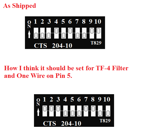
I was looking at my Grand Central Ethernet Unishield and saw that the dip switches were set in a non default way.

I want to maybe attach a TF-3 or TF-4 Filter in the future and thought the switches are no set properly. I also want the capability to add one wire probes off Pin 5.

I have attached a graphic of how it it set now and what I think it should be set to.

One addition question: The Grand Central VCC is a 3.3 v board. Will it run a TF-3 or TF-4?

Oakbarn Grand Central Uni.png
 
Nice!! Can be used in pictogram drawings (easier for some to read than schematics), and can be imported into a drawing program (like draw.io) as well.
I much prefer pics to schematics. I can read schematics but cannot draw them very well. I have tried various programs without much success. Too old a dog for new tricks!
 
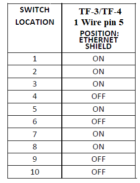
Should be per the product note. Assuming you have Ethernet, follow the last column.

If you want to put a 1-wire on port 5, and use the internal pull-up, then switch DIP switch location 7 to ON.

1647626047312.png


GC is 3.3V... TF-3 or TF-4 does not care about base voltage, just use 3.3V as the VCC there. I suggest your probes are shielded back to the control panel ground to reduce EMI as well.
 
Dip Switch 8 should also be ON for 1 Wire?
I do not know what Pin 5 Base does. Or for that matter and of the others to Base. Assume that those are special circumstances or do I need to worry about them if using an RP-3 for RTD Probes?
dip switch for TF-3 or TF-4 and One Wire on Pin 5.png
 
Connects the interface pin 5 to the Base board (terminates at 9-2). If this is ON then the screw terminal on the base (at 9-2, P pin) is connected to the interface. If not, then not.

DIP switch 8 should be on if you want to wire your 1-wire sensor at the base. Some people use a shield, in which case then you wouldn't.
OK I think I have it. For example Dip Switch 10 when "On" connects the Grand Central Pin/Port 10 the the Unishield and 7-3P and 7-3D are usable.

You would only want to do this if the Grand Central was connected serially (USB) as Pin 10/Port 10 is used for WiFi and Ethernet Connections if there is a shield installed { (N/C) on the Interface Wiring Map.}

If you have either an Ethernet or WiFi shield the Dip Switch 10 should be "Off" and 7-3P and 7-3D are NOT usable.

If connected via USB and Dip Switch 10 is "On", 7-3P and 7-3D can be D,O,P,R.

Pin 10 Base.png


In my case, since I want to be able to use 1 Wire probes, I would have Dip Switches 7 & 8 "On", allowing me to connect one wire proves to Pin 5/ 9-2P on the Unishield. Since I have an Ethernet Shield, Dip Switch 10 is "Off".

The last confusion I have is over Dip Switch 5, when "On" connects Pin/Port 7 to the Unishield 8-4P and 8-4D From the Interface Wiring Diagram, I can see that it must be "Off" for a WiFi shield, but could be used "On" with an Ethernet Shield or Serial (USB) interface (D,O,P,R). The reference to SPI is what confuses me.

If I was going to use an RP-3 RTD Board, should I leave Dip Switch 5 "Off"? When would you use PIN/Port 7 for SPI? It does not appear to be used in this schematic:
https://brucontrol.com/wp-content/uploads/2017/04/BruControl-RTD-via-SPI-Schematic.pdf
BTW, you have no schematics on wiring an amplifier board to a Unishield.
 
Yes, it looks like you have it correct except for the RP-3. Pin 7 is used for some wifi shields as the CS pin. Since the ethernet shield is does not use it, you can leave it ON. Wire the RTD board MOSI, MISO, and CLK to the terminals on the riser, then pick whichever pins you want for the CS pin, and wire those to the base P pins.

My recommendation... which I can't make enough... is draw a schematic of your wiring. Describing the wiring is a recipe for failure and burned up components!
 
I have three Crydom MCPC2450D Proportional Controllers that are 40-20ma type.

Any help on wiring would be appreciated.

This is the data sheet:
https://assets.alliedelec.com/v1575457953/Datasheets/48c0004eab09dfc0198ce5552c53fe3a.pdf
This is a previous post I made with a Diagram of my plan.
I have both the Crydom MCPC2450D Proportional Controllers and the 10PCV2425 Proportional Controllers. The 10PCV2425 Proportional Controllers are 0-10 v type but are rated at 25 amps.

I will be using a 5500 w Element?

If the Crydom MCPC2450D Proportional Controllers will work, I will use two of them on my HLT.

I would then use the 10PCV2425 Proportional Controllers for different Elements in the Quadzilla.

If they are not good, I will sell on EBAY.
 
Feature request. Fix the hide and also have an unhide command for a worksheet or just add the visibility property to a worksheet which would standardize how you treat them.


Would also be very nice to have a "path" command for Worksheet backgrounds, Element backgrounds and fileindex (wav) files. If I had that, I could make my "wort" flow on the screen and get rid of many Elements that are simply duplicated because of the 3 limit.
 
I have three Crydom MCPC2450D Proportional Controllers that are 40-20ma type.

Any help on wiring would be appreciated.

This is the data sheet:
https://assets.alliedelec.com/v1575457953/Datasheets/48c0004eab09dfc0198ce5552c53fe3a.pdf
This is a previous post I made with a Diagram of my plan.
I have both the Crydom MCPC2450D Proportional Controllers and the 10PCV2425 Proportional Controllers. The 10PCV2425 Proportional Controllers are 0-10 v type but are rated at 25 amps.

I will be using a 5500 w Element?

If the Crydom MCPC2450D Proportional Controllers will work, I will use two of them on my HLT.

I would then use the 10PCV2425 Proportional Controllers for different Elements in the Quadzilla.

If they are not good, I will sell on EBAY.

The MCPC2450D is indeed 4-20mA. You would have been better with the 'A' or 'C' variants, but it's not the end of the world. You will need a converter to convert PWM from the interface into the 4-20 mA signal for the SSR. Check amazon, for example something like this might cut it (I didn't exhaustively review): Amazon.com: Conversion Module Multifunctional PWM Signal to 0-20MA 0-3.3V/0-5V/0-10V Voltage to 0-20MA Plastic Metal Converter Module : Electronics
 
I'm having a problem locating one of my analog inputs. I am in the process of trying to create a workspace background and moving various devices to that new workspace. My HLT Volume sensor was successfully moved to that new workspace however while I was editing the style of gauge and location on the workspace I must have inadvertently deleted it. Ok no problem just recreate it and move on. Not so easy, I am unable to add a new device on pin A108, this is where it was and it is unavailable to assign. I looked to make sure the workspace is not locked and I have no hidden devices, and it doesn't appear on any other workspace. Anyway I was able to reinstall to another input A109 but not sure where the former pin ended up? Just trying to understand where all the unassigned-unavailable device pins end up?
Is there a way of taking inventory of the devices added to BruControl thru the device and what pins are available for assignment? I have an inventory Excell spreadsheet but wanted to see where the device is indicating A108 ended up.
Any thoughts on this would be appreciated.
 
Last edited:
The device element is hiding behind another one somewhere. This is why A108 is blocked - because it’s already assigned to the original device element. Need to find it.
If you are really stuck, you can email us the configuration file and we’ll dig it out for you.
 
I had a look on my workspaces and moved things around to see if it is hiding behind another element but no luck . I've sent my "Config File" to you, I can see it in the config file but not sure if it's as simple as editing the file to remove it and implementing the file as a new entry in the file log?
 
I had a look on my workspaces and moved things around to see if it is hiding behind another element but no luck . I've sent my "Config File" to you, I can see it in the config file but not sure if it's as simple as editing the file to remove it and implementing the file as a new entry in the file log?
This is a regular problem that I had. I have renamed every Element I have that includes the Workspace in the name.

I use the following for an Device Element Name.

1-3= Interface

MB_ = Main Brewery Mega Unishield
ES_ = ESP32
GC_ = Grand Central Unishield
NW_ = Not Wired Mega ( I use this to create pseudo Elements that are not wired off the interface, but use scripting to manipulate a real Element. I have five pumps and needed to control on different Workspaces, so I have both a real Yellow pump and a Pseudo Yellow Pump on different Workspace. I do this so the Elements look and act exactly the same on both Workspaces. Since a Mega 2560 is cheap, it was an easy decision. I also use Pseudo Elements to control some real Elements on the same workspace.


3-6 = Port/Pin

22_ = Port/Pin 22

7-10 = type
DB__ = Dead Band
di__ =Direct Input
DO__ = Direct Output
DCO_ Duty Cycle Output
HYS_ = Hysteresis
PID = Pid
rtd_ = SPI Input (RTD Temp Probe)
10K_ = Analog 10K Temp Probe
1wr_ = One Wire Temp Probe
fmA_ = Flow Meter Analog Input
fmH = Counter (Hall Effect Flow Meter)

and others if I need them

11- as needed

What it is

example: BrewKettleBurner_

Last 2 = Workspace

B1 = Main Brew Page
WT = water
FM = Fermenter Workspace
ALARM = Alarm Work Space
2B = Second Batch
and as needed.

As a specific example my Brew Kettle Burner (a solenoid gas valve that is a direct output) is on Port 22 of my Mega Uni Interface:

MB_22_do__BrewKettleBurner_B1


I then use the display name of Brew Kettle Burner.

The name has to be unique as you can only have one direct output on Port/Pin 22 of a single interface Interface and somewhat meaningless from a computer language view, but tells you a lot about it.

Application Elements are sorta the same:

tm_ = timer
alm_ = alarm
gblS = String Global Variable
gllV_ = Value Global Variable
gblT_ = Time Global Variable
gblB_ = Boolean Global Variable
gblDT_ = Date Time Global Variable
graph_ = graph
sw_ = switch
btn_ = button
inspect = inspector ( I do not use these as I find global do very well for this)

example: alm_FlavorHops1_ALARM

I try not to stack Elements so I that I cannot see them. I use the hiddenlocked attribute and never use the hidden attribute in scripting.

You could come up with your own system to make the names unique and tell you something about them at the same time. It was a pain to go back and change all references to a name when I changed it as I did not start to do this initially, but I finally figured out how to do it easily in Notepad++) After I changed my Element Names, I have had an easier time finding the
(As an aside, I could have a single Alarm Element that I could use for everything if I could change the path of Image 1 and File one, or at least one per Workspace! Personally, I could use just one for everything!!!)

I did lose one Device Element (a counter) that I have never found. It was early on in my setting up Brucontrol but I do not need it so no big deal as I changed my mind about installing Hall Effect flow meters.


It would be nice to have a screen print out of all your devices and what worksheet they were assigned to.
I have always kept the Element Name, associated PIN/Port , and Interface Name on an Excel spreadsheet but never thought of keeping an inventory of them on their respective "Workspaces" or if I have them "Hidden" or not. That would be especially helpful at this point for me as I've lost that 1 Analog Input somewhere on a "Workspace" even though it does appear in the "Config Backup Files" As you mentioned above I try to keep names unique as to avoid confusing them when it comes to scripting or moving stuff around. Thanks for providing the above information, it is very helpfull!!
 
I have always kept the Element Name, associated PIN/Port , and Interface Name on an Excel spreadsheet but never thought of keeping an inventory of them on their respective "Workspaces" or if I have them "Hidden" or not. That would be especially helpful at this point for me as I've lost that 1 Analog Input somewhere on a "Workspace" even though it does appear in the "Config Backup Files" As you mentioned above I try to keep names unique as to avoid confusing them when it comes to scripting or moving stuff around. Thanks for providing the above information, it is very helpfull!!
Here is the PDF of a spread sheet I use in Google Docs that will be glad to share as an Excel spreadsheet. Just PM me.
 

Attachments

  • Your Brewery_ Interface Name_ With Ethernet 45E+ - Sheet1.pdf
    132.4 KB · Views: 23
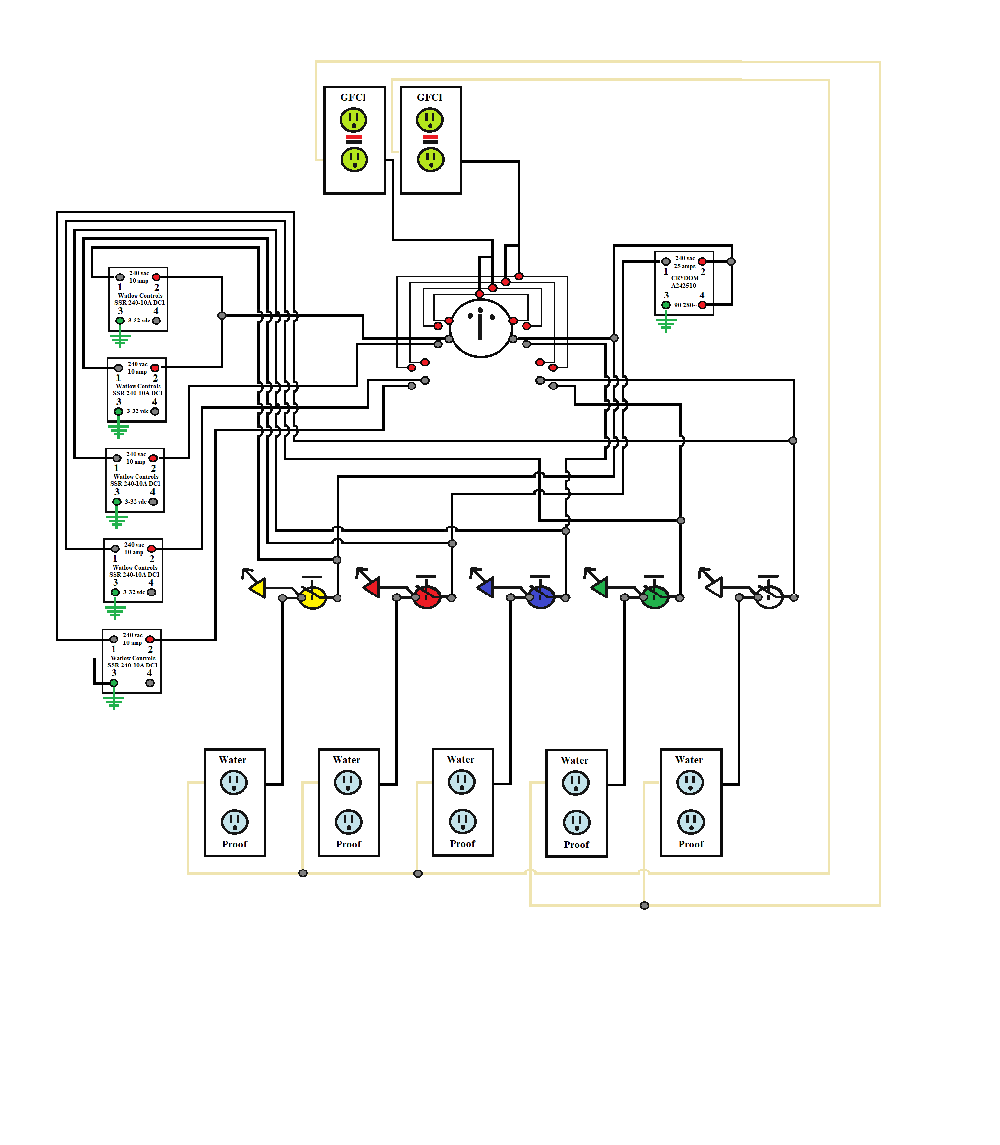
This is my plan for my Pump Control. I have 5 pumps and the Pump Box has SSRs and a Rotary Switch.
The Rotary Switch only has 4 Poles and The Positions. Position 1 feeds Power the 5 Watlow Control SSRs.
Position 2 feeds power directly to the 4 Colored Locking Push Button LED Switches and one Crydom A2425 (Load:240 vac 25 amp Control 90-280v~) and then to its Colored Locking Push Button LED Switch.
The Third Position turns off Power.
In Position 1:

I can have individual BruControl control of each SSR (and associated Pump) and also have manual On/Off via the Colored Locking Push Button LED Switch if the state = true.

In Position 2:

Manual On/Off via the Colored Locking Push Button LED Switch

Position 0:

All Pumps Off.

The question I have:

In Position 2, 110vac Hot is being fed back to the Load Side (Pin 1 of the Watlow SSRs). Is this an issue?

In Position 2, 110vac Hot is being fed to the Power (Pin 2 of the Crydom A2425) and the Control (Pin 4 of the Crydom A2425). The question I have is about Pin 3 which is normally the ground for the SSR. Should this be connected to the Ground of the GFCI Circuit or the Neutral?

The Datasheet is not clear: A2425 Crydom - Datasheet PDF & Technical Specs

pump Box.png
 
I am not sure what you looking to do here and cant venture any suggestions. I don't understand the drawing - (pictograms should not be used in place of schematics in my opinion). If you are building an automated system, why not let the software handle your switching and ditch unecessary physical controls?

That said, you don't let current flow through ground - your GFCI will trip. Your AC SSR need to have neutral on one end, not ground. The DC ones would be DC ground, which could be tied to AC ground, but no current will flow that way.
 
Sharing a cool board that a member posted on our forum... 11.05US $ 31% OFF|AC 90 250V ESP32 WiFi Bluetooth Ble Single Relay Module ESP32 Development Board ESP32 WROOM 32E|Integrated Circuits| - AliExpress

ESP32 based, with line-side power feed. Has breakout pins for other I/O (for example, to add a 1-wire sensor). Super easy way to make a fermenter controller: pop this in box, whack an extension cord in half and wire input and output... good to go! Only issue is does not have USB onboard, so needs a dongle for first firmware install.
 
The software will generally handle it on a Brew Day all though we have the option to manually kill the pump. We have planned lots of automation, but when transferring the Wort from thr MLT to the brew kettle and from the brew kettle to the fermentor, we shut off the pump when it cavitates from lack of supply.

Also, it is easier to tell a Brew mate to shut off the Red Pump on the panel.

I thought it should be the neutral instead of the ground.
 
Back
Top