BruControl: Brewery control & automation software

Homebrew Talk - Beer, Wine, Mead, & Cider Brewing Discussion Forum

Help Support Homebrew Talk - Beer, Wine, Mead, & Cider Brewing Discussion Forum:

This site may earn a commission from merchant affiliate links, including eBay, Amazon, and others.
I just got a 24"x24"x8" steel panel. I guess my build will be an electric 4 element with interlock to only operate 2 elements at once 240 volt 60 amp panel controlled by BruControl. It will be a slow project as I have to study other BruContro builds and read the information from their web site. Another adventure in the world of electic brewing !
 
We are going to demo a similar build - that may help you along the way. It will be 2 element, but you can basically double up the element circuits to get the power you need.

Depending on the automation you want to build in, a 24" square panel *may* be tight, especially if you create parallel circuits for the elements (bus -> 2x 25A circuit breakers -> 2x 30A contactors -> 2x 25A SSR's -> 2x elements vs. bus -> 1x 50A breaker -> 1x 60A contactor -> 1x 50A SSR -> 2x elements wired in parallel).
I kind of figured this panel would be tight for my system. I will most likely put a side car panel next to it. Also another idea is to use a regular 60 amp sub panel fed from a spa gfci panel. In the sub panel I can install 4-30 amp circuit breakers for the kettle heat elements. Feed 10 gauge wires from each circuit breaker to the main 24x24 panel. Just planning and designing outloud !
 
We are going to demo a similar build - that may help you along the way. It will be 2 element, but you can basically double up the element circuits to get the power you need.

Depending on the automation you want to build in, a 24" square panel *may* be tight, especially if you create parallel circuits for the elements (bus -> 2x 25A circuit breakers -> 2x 30A contactors -> 2x 25A SSR's -> 2x elements vs. bus -> 1x 50A breaker -> 1x 60A contactor -> 1x 50A SSR -> 2x elements wired in parallel).
As someone about to pull the trigger on a build, I'm wondering if there is an ETA for your demo of the build? Also, any plans to walk through all the features and possible application of your add ins for your Uniflex controller as you explained above?
 
As someone about to pull the trigger on a build, I'm wondering if there is an ETA for your demo of the build? Also, any plans to walk through all the features and possible application of your add ins for your Uniflex controller as you explained above?

The plan for the currently unnamed control panel (will be 50 amps) will be to film the planning and build of it. We would review the schematic, components, layout, and build in a step-by-step video series. I'm happy to take any feedback or requests from you on what you would like to see. I hope to start this next week.

For the UniFlex, I'll be doing a video walking through it from design to setup to brewing (will not actually brew with it - but working on having a brew-day video with it). Just trying to pull together all the pieces. This is probably within the next two weeks.
 
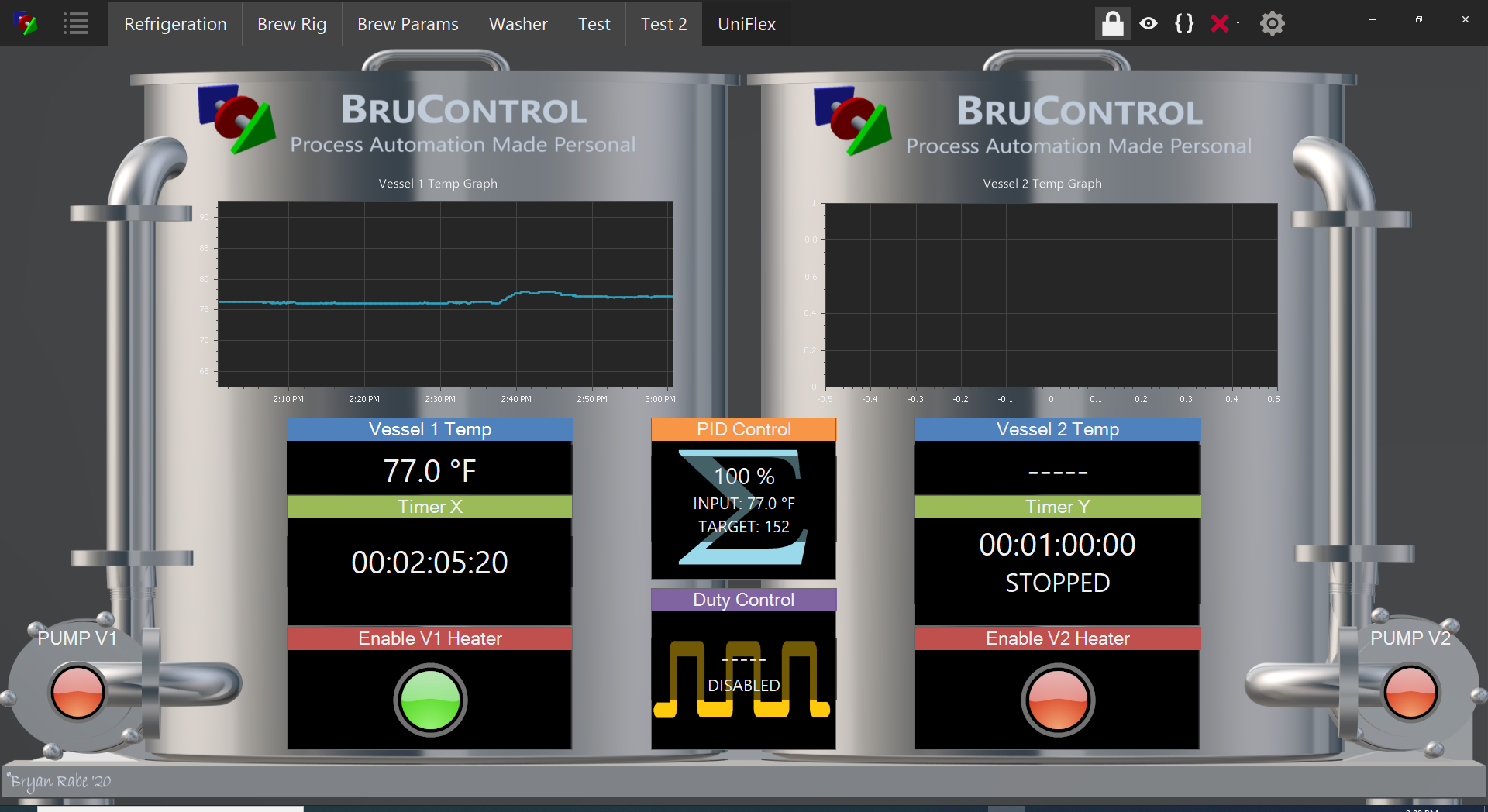
Initial look at the dual-vessel Workspace for the UniFlex. Need to add an alarm and maybe an I/O bank... plus the colors are a little cartoony but it needs to be clear and easy, so this is basic start. Suggestions appreciated!

We would provide to users to get started, then they can modify as they see fit. Sincere thanks to @Die_Beerery for the background graphic!

Workspace.png
!
 
My experience with the RTD amplifier boards is similar to @clearwaterbrewer in the fact that I suspect SPI bus or general chip power issues can also cause these spikes. I built a panel to use 4 amplifier boards and soldered up some headers on a perf board to mount the amplifier boards. I also had a local LCD display on this panel. When I powered all the 5V components from the mega's onboard LDO I would get similar temp spikes when I enabled and wrote to the display. I got similar spikes when one of my fridges would turn on/off in the garage. I changed the power for the amplifiers to a separate 5V supply and that fixed the LCD issue, but not the fridge spikes.

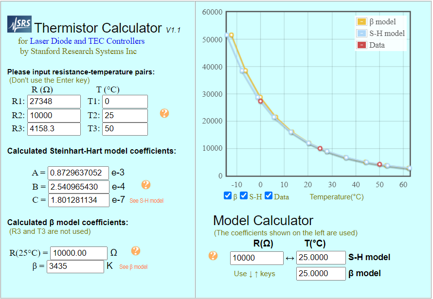
My main brew panel that is also mounted in my garage does not have any of these issues, but I use thermistors in that panel. I have found that as long as you use a 1% or better 10K reference resistor and some caps for filtering that thermistors are accurate within their 1% specification without having to individually calibrate each sensor/circuit. The biggest ***** is calculating the steinheart coefficients, but I found a small script in the interwebs that will calculate those for you from the resistance/temp table in the thermistor's datasheet.
I’m going through the S-H coeff headache right now. I’d be interested in that script. Right now I am within a couple degrees then trying to apply linear calibration to get it close to my 1-wire values which is less than ideal.
 
Thanks, it is a Vishay NTCLE413E2103F102L, R25=10K, 1%, Beta=3435

I just did a first pass, but you enter the beta to get the approximated curve, then enter three data values from the table (Table three from that device's datasheet) and get some approximated SH's. You might pick three values a bit higher in temp since that is where mashing occurs, but they need to be spread out for the calculator to work. Also, you need to convert the scientific notation to decimals for BruControl (sorry), so 0.872964 e-3 equals 0.000872964.

1591279053430.png
 
I’m going through the S-H coeff headache right now. I’d be interested in that script. Right now I am within a couple degrees then trying to apply linear calibration to get it close to my 1-wire values which is less than ideal.

Here is where I got the program from. thermistor.sourceforge.net

It takes in a text file of the entire temp/resistance curve. It will give a 4th order approximation, but you can ignore the 4th coefficient when entering the values in BruControl.
 
Here is where I got the program from. thermistor.sourceforge.net

It takes in a text file of the entire temp/resistance curve. It will give a 4th order approximation, but you can ignore the 4th coefficient when entering the values in BruControl.
Looks great, I don't have the expertise to get my data into that tool. Some day if I ever fire up Eclipse again I will try to tackle it
 
Super simple question compared to most on this thread it seems, but I have one of the PWM Topsflo TD5 3 wire PWM pumps from BrewPi. I hooked it up to a Meanwell 24vdc power supply (red to + black to -) and it wouldn't run at all. I assumed it would run at normal speed without PWM hooked up.

So I created a device and hooked up the blue wire to a PWM output (pin 9) from my Brucontrolled Mega2560, and the pump still does nothing.

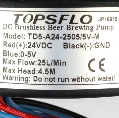
Here is the pump label-- it says the Blue Wire takes 0-5v. I thought the PWM from the mega should do the trick. Do I need to run this through a mosfet or?!? If so, confused on how to wire since the referenced schematic on brucontrol.com references a 2-wire DC pump to a mosfet, not a three wire like this one.

1591384318103.png
 
What components are needed for a cost effective volt amp meter display in BC?
 
Super simple question compared to most on this thread it seems, but I have one of the PWM Topsflo TD5 3 wire PWM pumps from BrewPi. I hooked it up to a Meanwell 24vdc power supply (red to + black to -) and it wouldn't run at all. I assumed it would run at normal speed without PWM hooked up.

So I created a device and hooked up the blue wire to a PWM output (pin 9) from my Brucontrolled Mega2560, and the pump still does nothing.

Here is the pump label-- it says the Blue Wire takes 0-5v. I thought the PWM from the mega should do the trick. Do I need to run this through a mosfet or?!? If so, confused on how to wire since the referenced schematic on brucontrol.com references a 2-wire DC pump to a mosfet, not a three wire like this one.

View attachment 683687

You have to make sure the mega gnd and the 24- are tied together.
 
Super simple question compared to most on this thread it seems, but I have one of the PWM Topsflo TD5 3 wire PWM pumps from BrewPi. I hooked it up to a Meanwell 24vdc power supply (red to + black to -) and it wouldn't run at all. I assumed it would run at normal speed without PWM hooked up.

So I created a device and hooked up the blue wire to a PWM output (pin 9) from my Brucontrolled Mega2560, and the pump still does nothing.

Here is the pump label-- it says the Blue Wire takes 0-5v. I thought the PWM from the mega should do the trick. Do I need to run this through a mosfet or?!? If so, confused on how to wire since the referenced schematic on brucontrol.com references a 2-wire DC pump to a mosfet, not a three wire like this one.

View attachment 683687
I can't seem to find any info on the PWM (frequency, currentt requirements, etc.). Do you have a spec sheet?

But per above, the grounds must all be tied together. This pump gets 24VDC power, and it sounds like the PWM should be 5V which is what the MEGA provides.
 
I can't seem to find any info on the PWM (frequency, currentt requirements, etc.). Do you have a spec sheet?

But per above, the grounds must all be tied together. This pump gets 24VDC power, and it sounds like the PWM should be 5V which is what the MEGA provides.

It will work with the Mega PWM signal. He doesn't have the GNDs connected, I guarantee it (ask me how I know). The device in BC will need to be set to 255 to get full power BTW.
 
What components are needed for a cost effective volt amp meter display in BC?

I used one from CR Magnetics for current. Works great: https://www.amazon.com/gp/product/B005CWOQV0/?tag=forumyield-20

Voltage is a little bit trickier, though it shouldnt be. I havent sourced one so I cannot confirm. CR Magnetics makes these too but they seem pricey. Loulensy makes them too. I would need to search and see. I never worried about mains voltage and only measured current because it really doesn't change much.
 
You have to make sure the mega gnd and the 24- are tied together.

Thanks @JoeyChestnutFan for that lead... turns out I "thought" I had them connected, but only one of the cables was actually secure in the wirenut. Once I stripped off some more cable, and reconnected, voila!

That said, you said 255 for full power? I am glad to hear that because the flow seemed very puny at 100 and I was seriously underwhelmed... Now learning this I want to test what the output looks like, but of course I have just unhooked everything! Tomorrow I will try it again and go to 255 and see what a difference that makes!

@BrunDog thanks for your input too.
If you want 0-100 run a multiplier.
 
Right now building a controller is very DIY and requires some integration know-how. I want to make it easier, so my apologies more isn't on the site yet. I will be working on more complete schematics along with Bill of Materials for those builds as guidelines.

That said, I would recommend an Arduino MEGA2560, a screw shield to go with it (I like one like this (serial connection only): http://a.co/jaE5OsT but you can also get it without the DIN mount), a 12V power supply, SSRs (as many as needed to run your elements), a 12V relay board (like this one: http://a.co/270vJ0h). Temperature probes are up to you... 1-wire is easiest and only require direct connection and one resistor, thermistors are also easy but require some supporting components, and RTD are the most accurate but require some supporting amplifier boards.
What voltage ssr's are required ? Most I see are 120 vac. Is something different better for a brucontrol system ? I have plenty of experience with 120/240 ac voltage. Now learning to use the low voltage hardware stuff or at least trying !
 
Most of the hockey-puck style SSR's we use in brewing go to 380 VAC on the switched side. On the switching side, we typically see up to 32VDC for DC devices (which we usually want since it is a low voltage controller providing that signal... so perhaps the limit you are seeing is 120VAC on AC devices? (again, we don't usually use these).
 
Most of the hockey-puck style SSR's we use in brewing go to 380 VAC on the switched side. On the switching side, we typically see up to 32VDC for DC devices (which we usually want since it is a low voltage controller providing that signal... so perhaps the limit you are seeing is 120VAC on AC devices? (again, we don't usually use these).
OK, use the same ssr's that many electric brew panels use with pid controllers. Just remembered that most brew panel pid's put out up to 32 vdc.
 
Most of these devices put out 5, 10, 12, or 24 VDC... just depends on the model. We take advantage of the lower end of the range... driving those SSR inputs with 5V if using a MEGA as your interface. I think we can get away with 3.3V if using an ESP32 or Grand Central. Or 12V if using a UniShield.
 
Looks great, I don't have the expertise to get my data into that tool. Some day if I ever fire up Eclipse again I will try to tackle it

No need for eclipse. Although the package contains the source, it also contains precompiled binaries. All you need to do is create a text file named 'simu.txt' with the temp/resistance table and put that in the same directory as 'coeff.exe'. Then from the command line you just have to run 'coeff.exe'. It will print out the coefficients to the console.
 
Ok, got a theoretical question I would like to get some thoughts on. I have finished my panel build and looking at making all my final fittings and connections between my brewing vessels. I have a three vessel system and I have fittings on my boil kettle and HLT to support adding pressure transducers to monitor vessel volume. I do not have a port on my mash tun to install a pressure transducer and would like to keep from putting another hole it if I don't have to. Any reason within BruControl that I could monitor the volume in my HLT via the pressure in that vessel during transfer of mash or sparge water from my HLT to mash tun by subtracting the amount from the total in the HLT rather than monitoring what is being added to the mash tun to get get my volume measurements? i.e when total pressure in HLT has dropped to the equivalent of the sparge volume, turn off the pump. Thanks for any thoughts or insights.
 
Yeah, just account for your piping losses and that would work. Any reason for not wanting a flow meter though? You wouldn't have to punch any holes for that to work.
 
Thanks @RiverCity. I had thought about that and had planned for two flow meters to keep track of my "flow" between HLT to Mash and Mash to Boil to make sure I was keeping correct volume above grain bed but I thought I had read somewhere that the pressure sensors were much more accurate for volumes than the flow meters and that was the main reason I was planning on the pressure transducers. I was just planning on using the flow meters to provide a "visual" representation of the run off and sparge rates within BruControl. Are the flow meters accurate enough for volume measurements during transfers?
 
Personally, I use both and run a script when transferring to track the delta of the two. If they get out of my defined range it alarms for me to check it out. As long as the flow meters are calibrated at a fixed flow rate, and then you always transfer at that rate, I would say they can be very accurate.
 

Latest posts

Back
Top