3bbl Electric Control Panel, power concerns.

Homebrew Talk - Beer, Wine, Mead, & Cider Brewing Discussion Forum

Help Support Homebrew Talk - Beer, Wine, Mead, & Cider Brewing Discussion Forum:

This site may earn a commission from merchant affiliate links, including eBay, Amazon, and others.

Rad-Rabbit

Well-Known Member
Joined
Aug 4, 2008
Messages
203
Reaction score
11
Location
Pennsylvania
Hi All,

I'm interested in constructing a control panel capable of 93gal-108.5gal (3bbl-3.5bbls). It needs to function on single phase 240v and be capable of running at least 4 (5500w-6000w) elements at a time. I would prefer to be able to run all 8 for back to back batches but even 3+3 would likely suffice for that propose. Yes, this is for a "would be" nano in a non-industrial area which is why I'm not talking 3 phase 240v or 480v.

I've done quite a bit of research and it seems that 60A (actually, I think I've come across an 80A but at this point that doesn't really help) is the likely the largest standard GFCI available. I'm fairly certain that NEC doesn't allow 4 separate supply feeds to enter the single control panel, but if it did, shouldn't it be (Please correct me if I'm wrong) as simple as adding 1 more 60A GFCI supply feed and additional (DIN breaker, contactor, SSR, ect) to the P-J drawings below to run 4 elements? Or removing the selector and adding 3 more 60A GFCI Supply feeds plus the additional (DIN breakers, contactors, SSRs, etc) to run all 8 elements? The E-Stop would function identical to the below schematic by adding 1-3 (depending on setup) add on NO Contacts to the original E-Stop to trip the additional GFCI's. Again, please correct me if I'm wrong.

Obviously life would be life would be simple if I could just build what I propose above but I just don't think that would function up to code. UNLESS, I installed 4-60A receptacles in the brew-house and the control panel wasn't hard wired, then the inspector wouldn't have to look into my control panel, but I digress.

How do I put this sucker together from a single HARD WIRED feed and do it safely? or do I just do the above proposal? I've been researching and I'm at a loss.

BTW- P-J, if you're reading this post, I'd like to thank you for all the help you provided in these forums. I have followed your posts for years, you are truly a great service to this community. Your drawings have been an inspiration to me and this project from the start.

Auberin-wiring1-a11b-RM-SYL-2352-5500w-s.jpg
 
I can appreciate wanting to put all your controls in a single enclose and powering it from a single AC power source. It would make a cleaner design.

However you might be able to build your system more cost effectively by using two separate 60 amp circuits, and three separate panels boxes


I am thinking two smaller power panels, each containing contactors, breakers, and SSRs to operate two heating elements.

The third panel would contain your PID controllers, low voltage control devices and everything else.

By only running low voltage SSR control voltages between the separate panels, I believe you would be NEC compliant.

In theory you could probably do this with just two enclosures. Power and control devices in one enclose and power device only in the second.

I may have missed some details that could make it unworkable, it's just a quick analysis.
 
I had given though to the option you suggested. It would take 2-4 Power panels and 1 control panel. I'm not opposed to this option the more I think about it. 1 panel would be nice buy who really cares as long as it works to code.
How can I add centralized E-Stop since all the power would be split into 2-4 power panels?
 
How can I add centralized E-Stop since all the power would be split into 2-4 power panels?

One way would be to add a main power contactor relay to each panel. You would also wire the the e-stop button to energize the coil of 3 or 4 pole single throw slave relay.

You would wire a set of dry contacts from this e-stop slave relay to switch the control voltage to the coils of each of your main power contactors.

When you hit the e-stop, the slave relay deenergizes, which in turn deenergizes all of the main power contactors, shutting down all loads.

If that all makes sense, great. Otherwise I might be able to sketch something up to show it.
 
First I'd like to say a big thank you for your reply and help.
EDIT
If it wouldn't be too much trouble a sketch would be of great use. Thanks again
 
After looking at your original diagram, I realized that the E-stop on that circuit operates by simulating a ground fault which opens the GFCI breaker feeding the panel.

If you supply your panel from two separate circuits with CFCI breakers, it would be very simple to duplicate the E-stop function for the second circuit with a two pole E-stop button instead of a single pole switch.
 
I don't think the leak current E-stop is going to work if we separate the power panels from the control panel. I can't think of a way the E-stop can trip all the GFCI's from a central location without having their power route through the single control panel. This is actually one of the reasons I initially wanted to try to make a single panel but after considering your first reply, splitting it into separate control and power seems to make more sense now.
 
Were are you finding that multiple conductors feeding a control panel is not NEC compliant?

You will need to take a commercial approach verses residential.

Seems to me:
The feeds will need to be enclosed in conduit. Flexible Water-Tite would work.
I would use Raintight disconnects within sight of the control panel (they can contain the GFCI)
They might frown on mobile units. Don't know.

If mobile:
For Plug-n-Go power cables, you're talking big bucks.
All Outdoor, Raintight and twist-loc.

Maybe you can recall seeing the wiring for a carnival, festival, outdoor concert, etc. It's all high current, multiple conductor cable.

It's late, I'll think about more options after a good sleep.

'da Kid
 
Hey thanks for your thoughts.
This is for a permanent hard wired setup and it is to be assumed that all components will be installed in their appropriate water tight enclosures etc.
I really don't know if commercial or residential code allows 4 separate 60A supplies hardwired to a single panel, it doesn't seem like it though. Temporary setups for carnivals and festivals I don't think really apply and I really don't want to get off topic.
I guess we can assume that there will be 1 control panel for switching and 4 60A power panels each supplying 2 heating elements for a total of 8 elements. I haven't wrapped my head around the E-Stop with this setup though.
 
The way the e-stop circuit is designed with currently limiting resistors and fused at 1 amp, I would not consider it a "power" application, and should allow sharing a common panel to provide e-stop control for 4 supply circuits.

I don't know if a electrical inspector would take the same view or not. It would probably be helpful to visit with someone who is better versed in the NEC as it applies to this project.
 
Would you be opposed to four 60A Spa Panels located within line-of-sight of the Control Panel?

I'm gonna have to do the research to find the rule against multiple branch circuits in a common panel. Seems totally foreign to me.

Here is my concern for 'after' the hard wiring. Your custom built Control will NOT be UL approved and in theory, the inspector can reject the approval.

Most of the inspectors in our area are happy to make a visit to address any concerns early in the process. On their schedule of course. They won't tell you how to perform the work, but will relay their requirements.

As for the control wiring, you can run it in the same conduit as the 240V. Your control voltages are from the same source as opposed to 24V and/or T/C wiring.

I'll need a better idea of your E-stop layout. One for the entire system? And/or one at each Power Box?

I'm happy to help get you closer to a solution,
'da Kid
 
Would you be opposed to four 60A Spa Panels located within line-of-sight of the Control Panel?

Here is my concern for 'after' the hard wiring. Your custom built Control will NOT be UL approved and in theory, the inspector can reject the approval.

I have wondered about brewers wanting to do a commercial installation with a custom panel without agency certification.

A sharp electrical inspector might balk at approving an installation with a "custom" panel without UL certification.

In some jurisdictions it might fly if the panel didn't have any flagrant code violations.
 
Not many of the panels have UL certification. Brewmation doesn't even offer it until you buy their $13,000 panel. I have so many examples of nano'a in PA without UL certification that I'm not really concerned about it.
I would be adding GFCI breakers to the main service panel so no need for spa panels. I just need to figure out how to centralize the E-stop. It's likely that separate power panels with be the route I take.
 
It'll probably look like a 15A 120v GFCI to the control panel and a 60A 240v GFCI to each of the control panels.
 
For the E-stop why not consider taking a standard industrial approach with the e-stop button feeding power to a e-stop contact(s) in the power panel (you already need to run control cable between the panels so another core to this shouldn't be too much of a hassle). Press the e-stop circuit opens and drops out the power supply to the system.
 
I'd reconsider the e-stop circuit if I were you. GFCI breakers are not designed to be continually tripped. They will wear out rather quickly using that design. I'd run a separate 120v circuit to control the coils of 4 separate 2 pole 240v contactors. Hit the e-stop in the 120v circuit and you just killed power to all 4 elements.
It's definitely going to cost a bit more up front but it's a hell of a lot better than replacing pricey 60a GFCI breakers.
 
Would you be as to draw the wiring for that circuit? I just can't picture it.

I think he is saying that each of your panels has a normally open contactor through which you run the hot lines, a double pole contactor for the 240v ones, a single pole contactor for the 120v one, all with 120v coils.

On the 120v panel, wire an e-stop in parallel to each of these contactor coils. When the e-stop is set to close the circuit, each of these contactors closes and allows power to its respective panel. When you hit the e-stop so no power flows to the contactor coils, you have effectively cut power to each control panel.
 
I'm happy to use the contactor e-stop instead of the GFCI E-stop, I thought that was clear since that's what I've been trying to redesign since the decision to split it into separate power panels. Using contactors to open the power circuits makes sense. It's how the actual E-stop circuit is wired in the control panel is throwing me, not the main shutoff contactor in the power panel.
I've been game for the contactor shutoff since Processhead suggested it in the 4th post, I'd just like to see how it's wired in the control panel. The explanations are not helping me visualize it.
 
I did some troubleshooting recently on a panel of similar scale, a three barrel, all electric, nano.

Their approach to the GFCI protection was to place a standard breaker box inside a larger than otherwise required control enclosure. Individual loads were all given their own GFCI circuit breakers in that breaker box.

The hard wired mains feed has a manual disconnect before the control enclosure to provide for safety lockout.

One downside to this approach is that you have to shut off and lockout the mains before opening the enclosure to reset a breaker. No worse than any other fuse or breaker in a control panel though.
 
I'm happy to use the contactor e-stop instead of the GFCI E-stop, I thought that was clear since that's what I've been trying to redesign since the decision to split it into separate power panels. Using contactors to open the power circuits makes sense. It's how the actual E-stop circuit is wired in the control panel is throwing me, not the main shutoff contactor in the power panel.
I've been game for the contactor shutoff since Processhead suggested it in the 4th post, I'd just like to see how it's wired in the control panel. The explanations are not helping me visualize it.

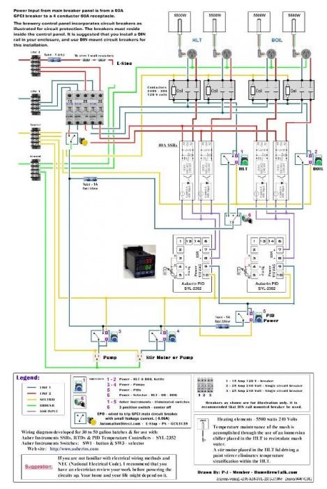
Sorry that my drawing skills are not good enough to provide a visual, but perhaps this will help until someone more skilled can chime in. Here's one way to do it.

Let's say you want each control panel to have a main power switch, and your 120v panel has that plus an e-stop switch that controls all the control panels. All these switches are 120v.

120v power line goes into the 120v panel. Wire the hot to the line side of your contactor, then through the e-stop, then through the main power switch, then to the contactor coil. Wire the neutral to the contactor coil. Also wire the neutral in parallel from the power line to your neutral bus to feed the 120v panel. Wire a hot from the load side of the contactor to your hot bus. So now both the e-stop and the main power switch must be closed for your hot bus to be energized.

Now you are going to wire a 120v feed from your 120v panel to each of your 240v panels, and wire each of them as follows. Wire the hot through the main power switch, then to the contactor coil. Wire the neutral to the contactor coil. For your 240v feed into the 240v control panels, wire each hot to a line terminal of the contactor, and out the load terminal to however you want to distribute hot 1 and hot 2. If you have a neutral in you 240v feed, wire that into your neutral bus. So now in each 240v panel, you will need a closed circuit from the 120v panel and a closed main power switch to energize the contactor coil and close the circuits for your 240v hots.

In summary, your 120v panel is only "on" if the e-stop and main power switch are closed. Each 240v panel is only "on" if its main power switch is closed, and the 120v panel is "on." Hit the e-stop on the 120v panel and each contactor in each panel is de-energized, so the power is cut to each panel at the line in of the contactor. Note that with this configuration, you always have hot lines at the line terminals of the contactors, at the e-stop, and at the main power switch of the 120v panel when the e-stop is closed.

I hope this helps.
 
Note the relocation of the e-stop button. The e-stop switch would also need to be a NC switch to function correctly.

Opening this circuit would shut down all active kettles, pumps, etc.

Auberin-wiring1-a11b-RM-SYL-2352-5500w-s.jpg
 
No.

This is not a momentary push-button switch.

"red-mushroom" type e-stop switches are a latching push button switch.

You smack them at crunch time and they stay in the desired state until the issue is resolved.

Then you physically pull them back out to the "normal" state and the system is ready to operate.
 
Note the relocation of the e-stop button. The e-stop switch would also need to be a NC switch to function correctly.

Opening this circuit would shut down all active kettles, pumps, etc.
Thanks. I redrew the diagram to illustrate your suggested layout. I think it is a very viable plan - So Thank You for that.

And as always click on the image to see and save a full scale diagram printable on Tabloid paper (11" x 17")


I hope this is of some help.

I've also been scheming out how to draw a plan for the desired 3 barrel system. Still scratching my old man's head but will figure out the layout - Hmmmm...

P-J

Edit: The E-Stop from Auber Instruments:
This is a 22mm emergency stop (E-Stop) switch. Press it down to stop the operation in the event of emergency. Twist it and release it to turns it on again.
1 normally open and 1 normally closed contact blocks included.
Rated current: 10A.
 
Thanks P-J! I'm sure you'll figure out how to power the 8 elements. I viable plan has proved challenging to say the least. I promise that if you draw it I will build it!
 
I suppose I should make it clear that I appreciate everyone's contributions to this thread. Thank you all so far. As soon as their is a complete plan I will order all the components to build it ASAP. I will share the photos of the build as well.
 
I don't know the exact requirements, but I believe so long as the panel is identified as being served by multiple circuits and necessary blah, blah, blah you should be all set feeding the cp with however many 60A gfci curcuits you need. two (2) 5500w or a 6000 & 5500 element (60A*.8=48A*240V=11520W) is all you will be able to power from each circuit, so figure the total elements you want in the vessels and that will define how many breakers you need. I don't know how NEC and the inspector are going to look at switching source power between elements, but so long as you have appropriate circuit protection I would think you are good (so says the mech eng...). If it was me I would want 4 elements in both the HLT and boil kettles to speed up heating times, because even with 23Kw it is going to take you over an hour to get 100 gallons from 55* to 170* and 45 minutes from 1508 to boil, so I would be designing a panel with 2 60A circuits each for the HLT and Boil. What are you doing to maintain mash temps? RIMS, HERMS? Sounds like you are set on breaking the feed out of each breaker with a 60A contactor via the e-stop so I would move the contactors from the out side of the SSr's to in side, right after the breaker.
 
WPStrassburg

I'm not sure if you got a chance to read the entire original post but 4 elements per vessel has been the plan since the beginning. 8 elements, 22kw-24kw total each vessel. I'd like to run all of it at once for back to back batching. No heating in the MLT, I don't want it. If I change my mind I'll add a HERMS later.
 
...
I'm not sure if you got a chance to read the entire original post but 4 elements per vessel has been the plan since the beginning. 8 elements, 22kw-24kw total each vessel. I'd like to run all of it at once for back to back batching. No heating in the MLT, I don't want it. If I change my mind I'll add a HERMS later.
Well after many hours of planning, pondering and puzzlement - I've come up with a diagram set that should work for you.

If you see anything that is not clear, Please ask & I'll do my best. There are 2 diagrams. The first is for the HLT setup and pump control. The second is for the BOIL control. The overall power feed is from 4 - 60A - 240V power feeds plus a seperate breaker for the 120V devices.

As always click on the images to see and save the full scale diagrams that is printable on Tabloid paper (11" x 17")

HLT & control setup:


BOIL setup:


I hope this is of some help for you.

P-J
 
Hmmmmm..... After a looking at the diagrams after I posted them, It's possible that the same thing can be done with a total of 2 pids instead of 4. One for the HLT set and one for the BOIL set.You would still need the multiple sets of SSRs. I really would have to do some more brain storming to be sure though.

But: Maybe having independent control over each set of 2 elements is a good thing?

Oh well....

P-J
 
I'd vote for one controller each tank.
The PID parameters should be able to tune it in.

If not.

You could also have a couple SSR's tied to an alarm output.
The alarm setting is "50degF below setpoint"
When the temp is 50degF below setpoint, the alarm is ON and two additional SSR's are on. Once the temp arrives at 49degF below setpoint, the alarm is OFF as are two SSR's/elements.

50degF is just a number I pulled out of my . . . . . . :eek:


'da Kid

PS: Nice work P-J
 
Hmmmmm..... After a looking at the diagrams after I posted them, It's possible that the same thing can be done with a total of 2 pids instead of 4. One for the HLT set and one for the BOIL set.You would still need the multiple sets of SSRs. I really would have to do some more brain storming to be sure though.

But: Maybe having independent control over each set of 2 elements is a good thing?

Oh well....

P-J

Thanks P-J, the drawing looks great, I owe you!
I'd definitely prefer to use 2 PIDs instead of 4 though.

To use just two PID's, I would run the SSR's for elements 3&4 from a single PID output 7&8 in parallel, right?
Did we figure out if the panel is allowed to have 4 supply feeds?

A few more things:
The second 5A breaker doesn't go anywhere. Could you please clarify it's purpose? Could I add a contactor and put the pumps on that breaker and leave the PIDs on the other? I'm assuming you put it there for a specific purpose.

Thanks again and everytime!
 
I'd stick with the 5500W Rad

At 5500W x 2 elements, you are going to be at about 80% load on your breaker.

That's a good safe percentage to be at.


Did you ever research the BTU's needed for your 100gal tank?

I've seen the formula(s) here somewhere.

'da Kid
 
I'd stick with the 5500W Rad

At 5500W x 2 elements, you are going to be at about 80% load on your breaker.

That's a good safe percentage to be at.


Did you ever research the BTU's needed for your 100gal tank?

I've seen the formula(s) here somewhere.

'da Kid

The10mmKid
Each set of elements have a 60A breaker, 80% is 48A. I guess since a set of 6000W elements would have a max draw of 50A you are technically correct. A set of 5500W elements would have a max draw of ~46A (45.83A)

Heating times.
I did it by hand since the online calculator is down. 100gallons from 55 to 170 @24kw will take 1h15m or 1h23m @ 22kw. But this isn't a very big deal since I would likely fill the HLT the night before, that would raise the temp from 55 to ~65 (lowering the time) and I would be doing prep for an hour or so after turning on the HLT in the morning. By the time I would be ready to dough in, the water would be ready also.
 
I used 230V for calculating.

Don't let me talk you out of the 6000W'ers
Also, you wont get the 'design' wattage at a reduced voltage. Performing an amp draw is the only true test.
Your 'real world' math may be:
5750W/232V

I'm just performing our usual math so that when I finish a job, I know there is a little more wiggle room and I haven't wired a project that I will worry about next month, next year.

'da Kid

No problem, while doing the calculations, boil times change by less then 4 minutes and HLT times by ~7minutes between the two, either way not a very big deal. I'll through a meter on the supply for sure. There are still a few things that need clarity still before I start ordering components.
 
Happy to pass along any info I may have.

Tonight I worked on a 36Kw walk in curing oven. The temp. controller output relay stuck on and the separate Overtemp Safety controller caught it and released the heater power relay.

3-phase, 480V, 40A Mercury Displacement Relay.

Old thing. I want my boss to spend money on SSR's, but the MDR's are still cheap. Must still be a bunch of mercury out there. :cross:

'da Kid
 
Back
Top