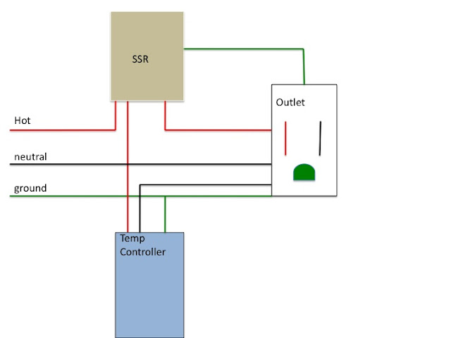
I've built a temp controller that's using an Auber temp controller, a 10amp SSR, and an outlet for my temp controller. Freezer plugs into outlet. When the controller tells the SSR to kick on, i get perfect 110 at the outlet. When the controller turns off the SSR, I'm getting 50volts to the outlet. I'm powering the temp controller and the outlet all through one 110v connection. What am I doing wrong. It's not an easy picture to take the way it's packed together, but I'll get one up this evening anyway. I'm getting ready to start brewing my Octoberfest and I want to use my new ferm chamber.
Flananuts
Flananuts