I am trying to work out the details of my new rig. I have built a PWM circuit to control my BK temps. Now I need to figure out a good solution for monitoring temp in the BK and MLT. I would like to panel mount a digital display to read the temps. Most of the panel mounts I have found are more expensive then a PID. A PID seems overkill for just reading temp.
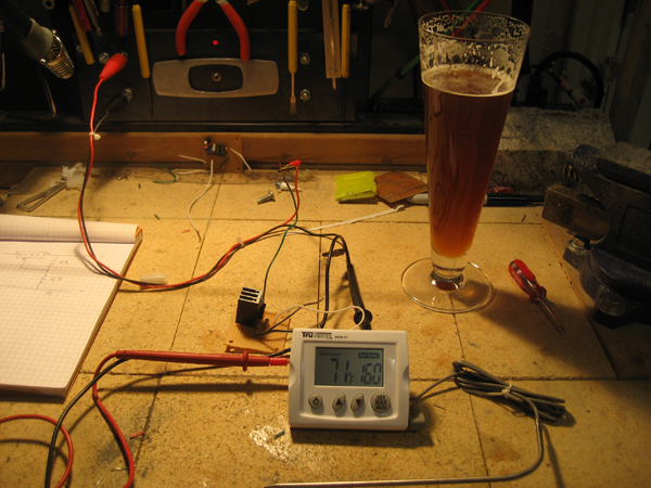
My other thought was to buy a couple of Digital thermometers from wally world and tear them apart and mount the LCD on my panel. Then I thought I could just make one.
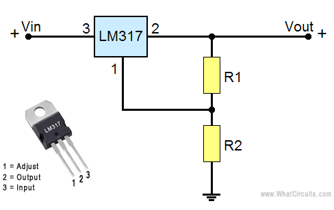
Any thoughts on this? I have not found a good schematic yet so I am a bit hesitant.
My other thought was to buy a couple of Digital thermometers from wally world and tear them apart and mount the LCD on my panel. Then I thought I could just make one.
Any thoughts on this? I have not found a good schematic yet so I am a bit hesitant.