bdjohns1
Well-Known Member
P-J,
I'm trying to locate one of your older wiring diagrams - but apparently I can no longer just browse the index of your images folder. I've been lurking for a while in "sponge mode" just soaking up ideas.
I'm looking for one of your existing diagrams that basically covered a scenario like this just to sanity check myself - I don't want you to go to the extra time to re-draw anything. If I can't assimilate the concepts from your different diagrams, I figure I shouldn't be playing.
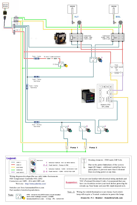
Supplied from 50A GFCI spa panel, but upstream breaker is 30A, so that's the real limiter.
2x 4500 or 5500 W elements (HLT and BK)
A 3-pos selector switch (2x NO blocks, maintained L/R, center off) to enable only one element - http://www.grainger.com/Grainger/SIEMENS-Selector-Switch-6FPJ8
The selector switch is 120V, going to the coils on a couple of DPDT relays - so that the element not in use is 100% cut off - the SSR output leg goes to one side of the relay, and the other hot line is on the other side.
40A SSRs driven off separate Auberins PIDs
2x March 120V pumps
120V SPST toggles for the pumps and PID power.
Here's the relays I'm using - http://www.grainger.com/Grainger/DAYTON-Relay-1EJG7 - rated for 30A resistive load up to 277VAC.
If I remember right, the correct way to do this is to put the relay between the SSR and the element for the hot leg supplied from the SSR - basically, the same design you do using Auber's contactors.
I'm trying to locate one of your older wiring diagrams - but apparently I can no longer just browse the index of your images folder. I've been lurking for a while in "sponge mode" just soaking up ideas.
I'm looking for one of your existing diagrams that basically covered a scenario like this just to sanity check myself - I don't want you to go to the extra time to re-draw anything. If I can't assimilate the concepts from your different diagrams, I figure I shouldn't be playing.
Supplied from 50A GFCI spa panel, but upstream breaker is 30A, so that's the real limiter.
2x 4500 or 5500 W elements (HLT and BK)
A 3-pos selector switch (2x NO blocks, maintained L/R, center off) to enable only one element - http://www.grainger.com/Grainger/SIEMENS-Selector-Switch-6FPJ8
The selector switch is 120V, going to the coils on a couple of DPDT relays - so that the element not in use is 100% cut off - the SSR output leg goes to one side of the relay, and the other hot line is on the other side.
40A SSRs driven off separate Auberins PIDs
2x March 120V pumps
120V SPST toggles for the pumps and PID power.
Here's the relays I'm using - http://www.grainger.com/Grainger/DAYTON-Relay-1EJG7 - rated for 30A resistive load up to 277VAC.
If I remember right, the correct way to do this is to put the relay between the SSR and the element for the hot leg supplied from the SSR - basically, the same design you do using Auber's contactors.